Steam turbine and method of cooling steam turbine

a steam turbine and steam turbine technology, which is applied in the direction of machines/engines, liquid fuel engines, engine starters, etc., can solve the problems of large thermal capacity of time for heating casings, difficulty in reducing thermal expansion differences, and difficulty in reducing start-up time, so as to reduce the start-up time and reduce the thermal expansion difference

Inactive Publication Date: 2010-01-14
KK TOSHIBA
View PDF7 Cites 20 Cited by
  • Summary
  • Abstract
  • Description
  • Claims
  • Application Information

AI Technical Summary

Benefits of technology

[0013]The present invention provides a steam turbine which can decrease a thermal expansion difference between a turbine rotor and a labyrinth portion in the axial direction of the turbine rotor and which can decrease a start-up time, and a method of cooling a steam turbine.

Problems solved by technology

But, since the above-described conventional steam turbine, which heats the flange portion of the casing by steam at the start of it, is provided with a mechanism of heating the casing, it has a disadvantage that the casing has a complex structure.
Since a large amount of steam was required to heat the casing having a large thermal capacity, improvement of the steam turbine efficiency was hindered.
Besides, time for heating the casing having a large thermal capacity is required, and there was a problem that it took time to start the steam turbine.

Method used


Image

  • Steam turbine and method of cooling steam turbine
  • Steam turbine and method of cooling steam turbine
  • Steam turbine and method of cooling steam turbine

Examples


Embodiment Construction

[0038]One embodiment of the present invention is described below with reference to the drawings.

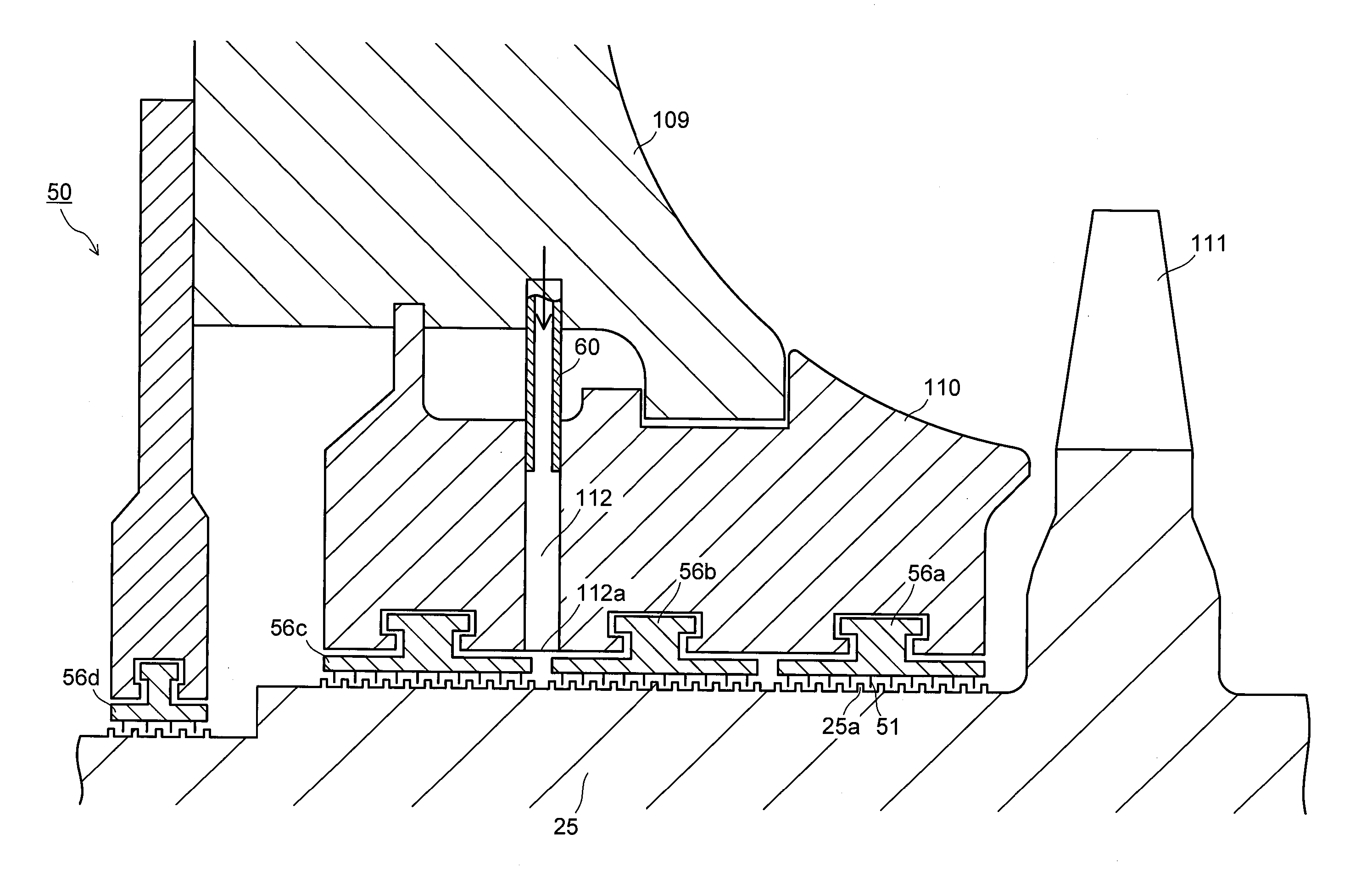
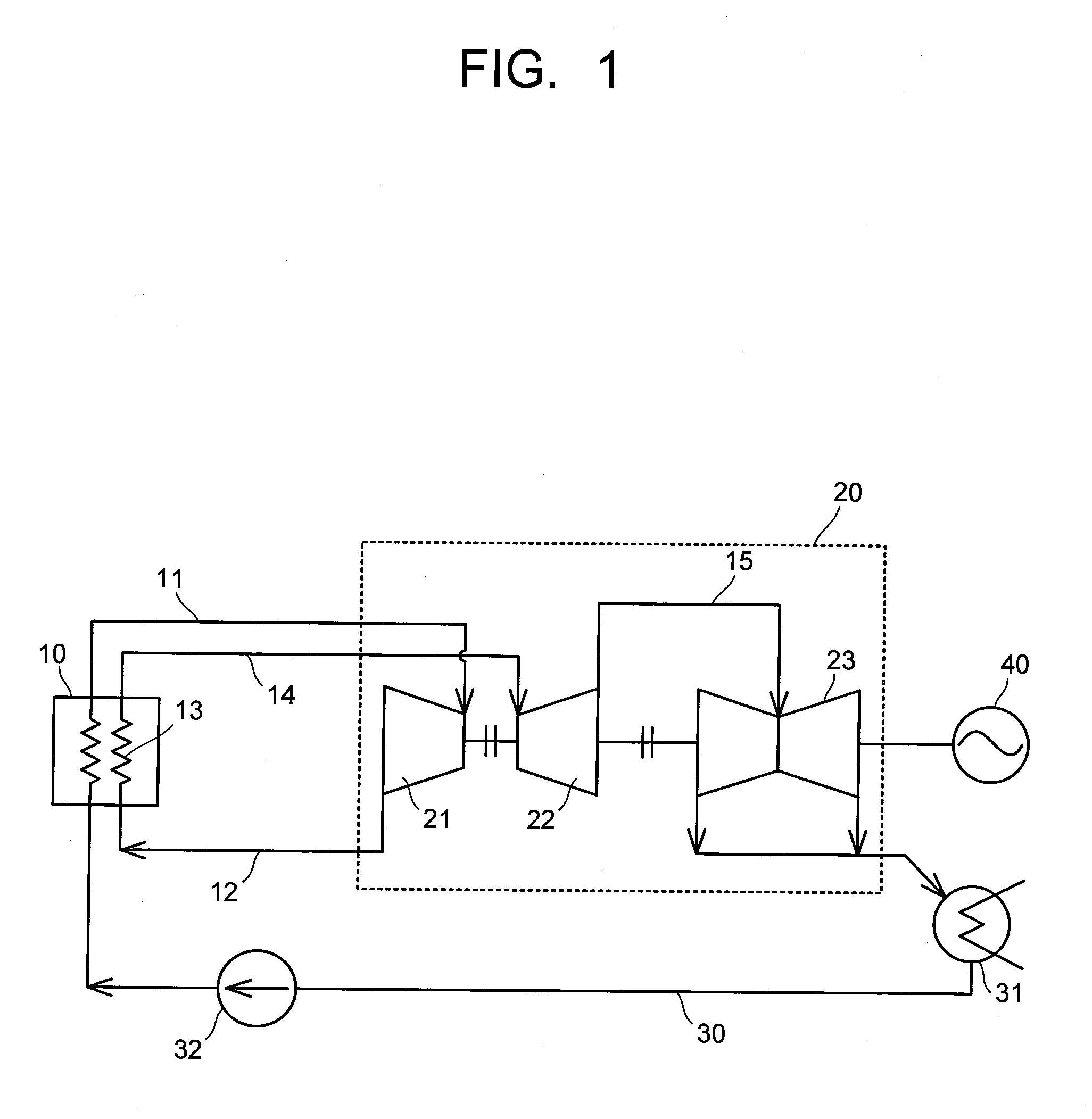
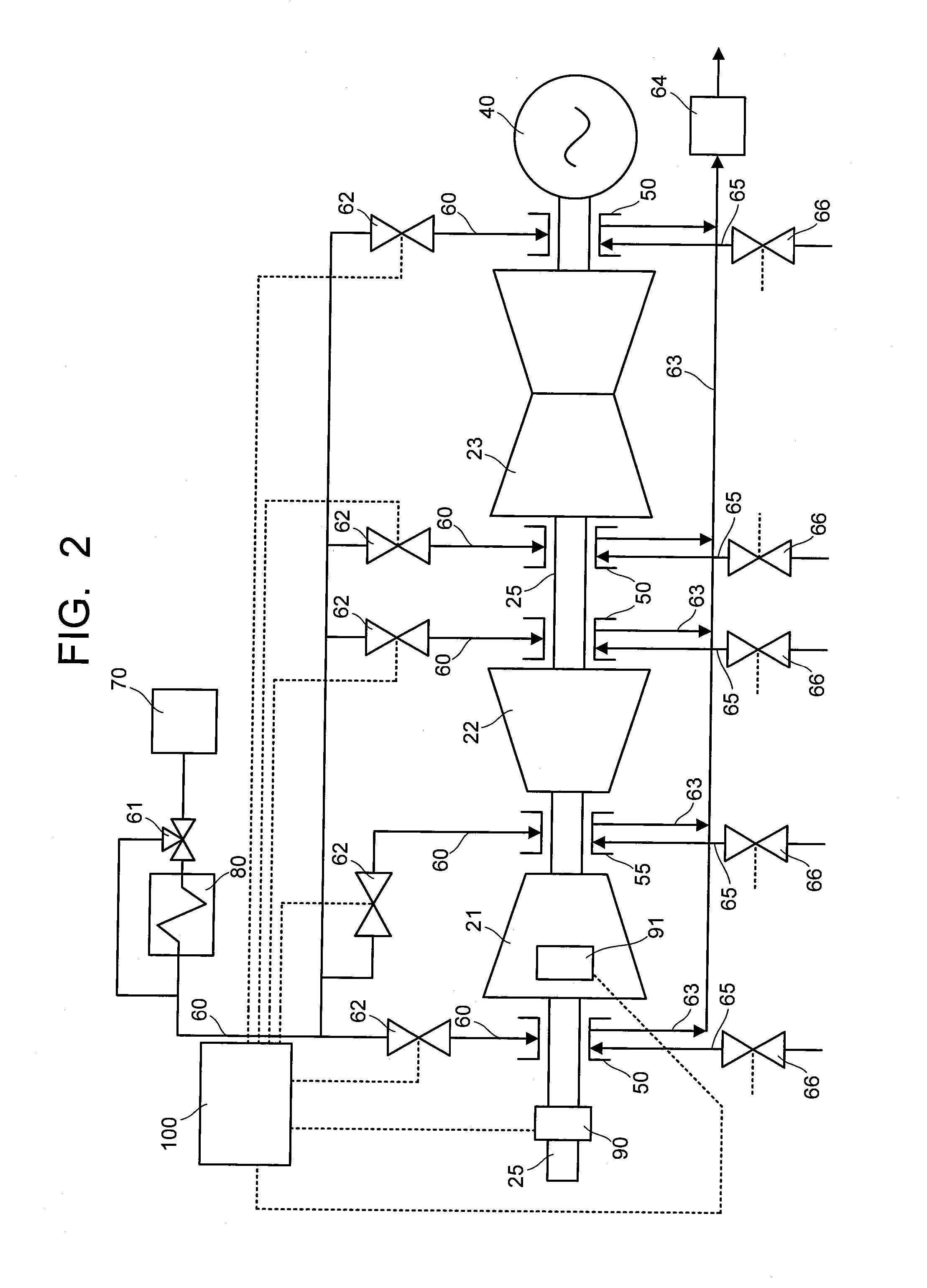
[0039]FIG. 1 is a diagram showing an outline of an example of a power plant provided with a steam turbine 20 according to an embodiment of the invention. FIG. 2 is a diagram showing an outline of an example of a gas supply system which supplies a cooling gas or a heating gas to a labyrinth portion of the steam turbine 20 according to an embodiment of the invention. FIG. 3 is a diagram showing an example of a cross sectional structure of the labyrinth portion.

[0040]As shown in FIG. 1, a power plant is configured by combining a steam generator 10, which consists of a boiler and the like, with the steam turbine 20 and a condensate supply system 30.

[0041]The steam turbine 20 provided in the power plant includes a high-pressure turbine 21, an intermediate-pressure turbine 22 and a low-pressure turbine 23, and the steam turbine 20 and an electric generator 40 are axial connected through a turbi...


PUM


Abstract

A steam turbine 20 is provided with a casing 109, a turbine rotor 25 disposed through the casing 109, and labyrinth portions 50, 55 which are disposed at the boundary between the casing 109 and the turbine rotor 25. The steam turbine 20 is further provided with a sealing steam pipe 65 for supplying sealing steam to the labyrinth portions 50, 55 and a gas supply pipe 60 for supplying the labyrinth portions 50, 55 with a cooling gas for cooling the turbine rotor 25 or a heating gas for heating the turbine rotor 25.

Description

CROSS-REFERENCE TO RELATED APPLICATIONS[0001]This application is based upon and claims the benefit of priority from the prior Japanese Patent Application No. 2008-181626, filed on Jul. 11, 2008; the entire contents of which are incorporated herein by reference.BACKGROUND[0002]1. Field of the Invention[0003]The present invention relates to a steam turbine, which is capable of cooling or heating a turbine rotor by air or the like, and a method of cooling a steam turbine.[0004]2. Description of the Related Art[0005]Generally, during a start-up of a steam turbine, a turbine rotor, lots of parts of which are directly exposed to high-temperature steam, has a quick temperature increase, while a casing, having a large thermal capacity, has a slow temperature increase. Here the casing means stationary portions of the steam turbine.[0006]FIG. 20 is a diagram showing a thermal expansion difference, which is a difference between an axial expansion amount of the turbine rotor and an axial moving...

Claims


Application Information

Patent Timeline
Patent Type & Authority Applications(United States)
IPC IPC(8): F01D25/12F01D11/08F01D21/04
CPCF01D11/02F01D11/04F01D19/00F05D2240/55F01D25/08F01D25/10F01D25/12F01D21/12
Inventor INOMATA, ASAKOYAMASHITA, KATSUYAYAMAGUCHI, KOJI
Owner KK TOSHIBA
Why Eureka
Try Eureka