Liquid jet surgical instrument having a distal end with a selectively controllable shape

Inactive Publication Date: 2010-01-14
HYDROCISION
View PDF6 Cites 148 Cited by
  • Summary
  • Abstract
  • Description
  • Claims
  • Application Information

AI Technical Summary

Benefits of technology

[0009]In one aspect, the invention provides a surgical instrument having a distal end adapted to perform a surgical procedure on a patient and a proximal end. The instrument includes a pressure tube having sufficient burst strength to conduct a high pressure liquid towards the distal end of the instrument, where the pressure tube includes at least one nozzle providing a jet opening, the nozzle being shaped to form a liquid jet as the high pressure liquid flows therethrough. The instrument further includes an evacuation tube including a jet-receiving opening locatable opposite the jet opening, where the nozzle is aligned with the jet-receiving opening to receive the liquid jet when the instrument is in operation. At least the distal ends of both the pressure and evacuation tubes have a first configuration in a non-relaxed state and a second configuration in a more relaxed state. A straightener is constructed to selectively control the configuration of the distal ends of both the pressure and evacuation tubes to change one or more of the radius of curvature of the distal ends of both the pressure and evacuation tubes, the arc length of a curved portion of the distal ends of both the pressure and evacuation tubes, and the angular orientation with respect to a longitudinal axis of the proximal end of the surgical instrument of both a center line of the nozzle and a center line of the jet-receiving opening.
[0010]In yet another aspect, the invention provides a method comprising inserting at least a portion of a surgical liquid-jet instrument comprising a distal end adapted to perform a surgical procedure on a patient and a proximal end into a surgical site in the body of a patient. Relative motion between a straightener and a pressure tube and an evacuation tube of the surgical liquid-j et instrument is created where at least the distal ends of both the pressure and evacuation tubes undergo bending or straightening as the straightener and the pressure and evacuation tubes are moved relative to each other. One or more of the radius of curvature of the distal ends of both the pressure and evacuation tubes, the arc length of a curved portion of the distal ends of both the pressure and evacuation tubes, and the angular orientation of the center lines of both a nozzle in fluid communication with the pressure tube and a jet-receiving opening of the evacuation tube with respect to a longitudinal axis of the proximal end of the surgical instrument changes as the tubes bend or straighten. A liquid jet is created with the surgical liquid-jet instrument by flowing a liquid under high pressure through the nozzle in fluid communication with the pressure tube and the liquid jet is directed towards the jet-receiving opening of the evacuation tube of the sur

Problems solved by technology

Typically, these prior art instruments suffer from a variety of disadvantages.
For example, the instruments can be slow and laborious to use, typically they lack the ability to selectively differentiate tissue to be excised from non-target tissue, they tend to have sizes and/or shapes which make access of many surgical sites difficult, and they tend to cause unintended damage to tissue surrounding the intended target tissue.
For many minimally invasive surgical applications such as arthroscopy, certain spinal procedures etc., where visualiza

Method used


Image

  • Liquid jet surgical instrument having a distal end with a selectively controllable shape
  • Liquid jet surgical instrument having a distal end with a selectively controllable shape
  • Liquid jet surgical instrument having a distal end with a selectively controllable shape

Examples


Embodiment Construction

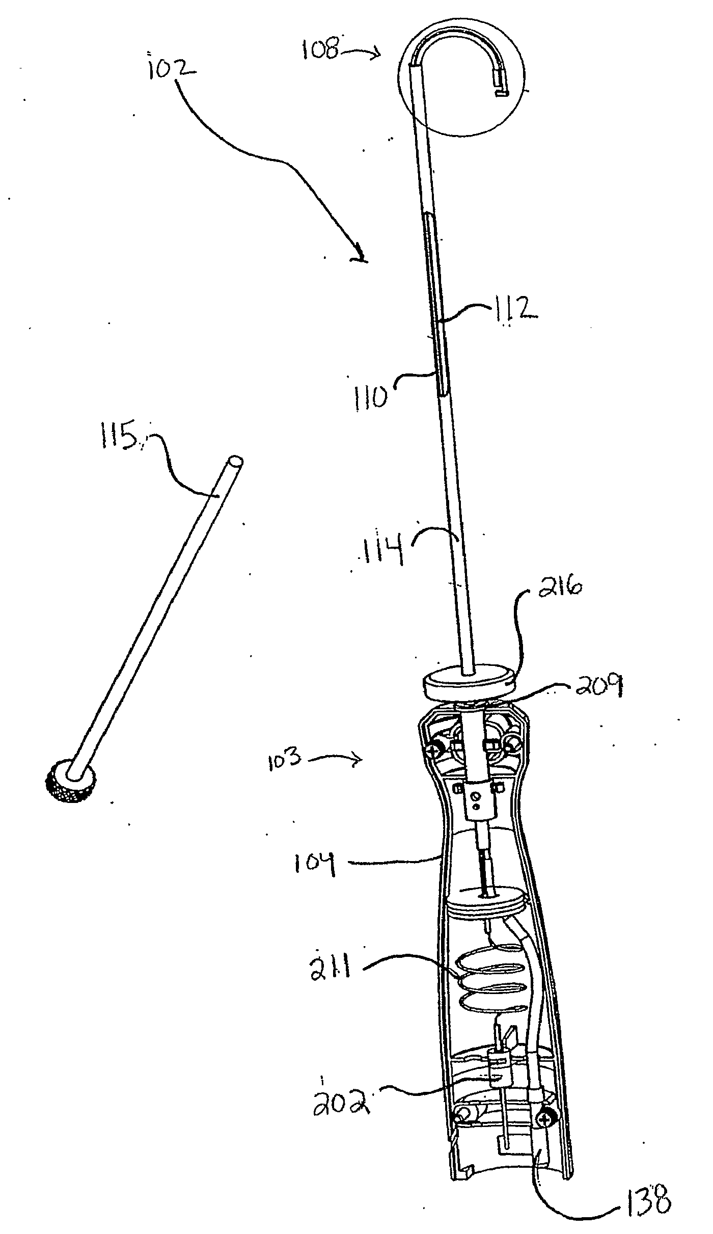
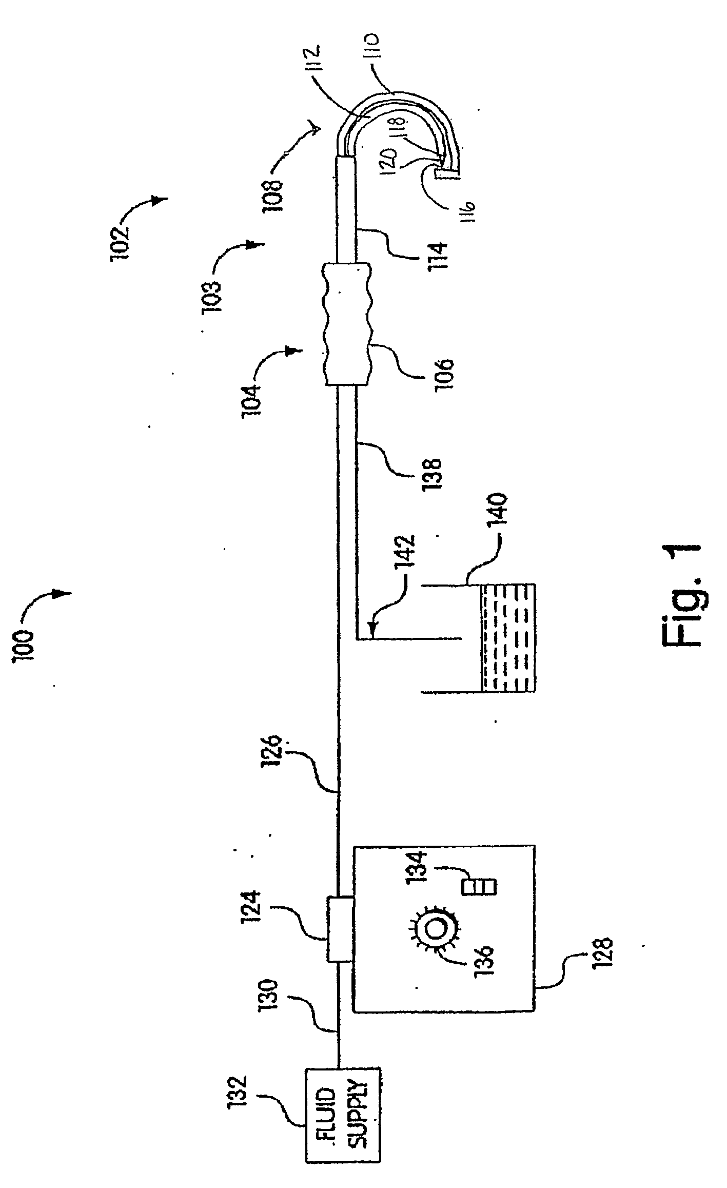
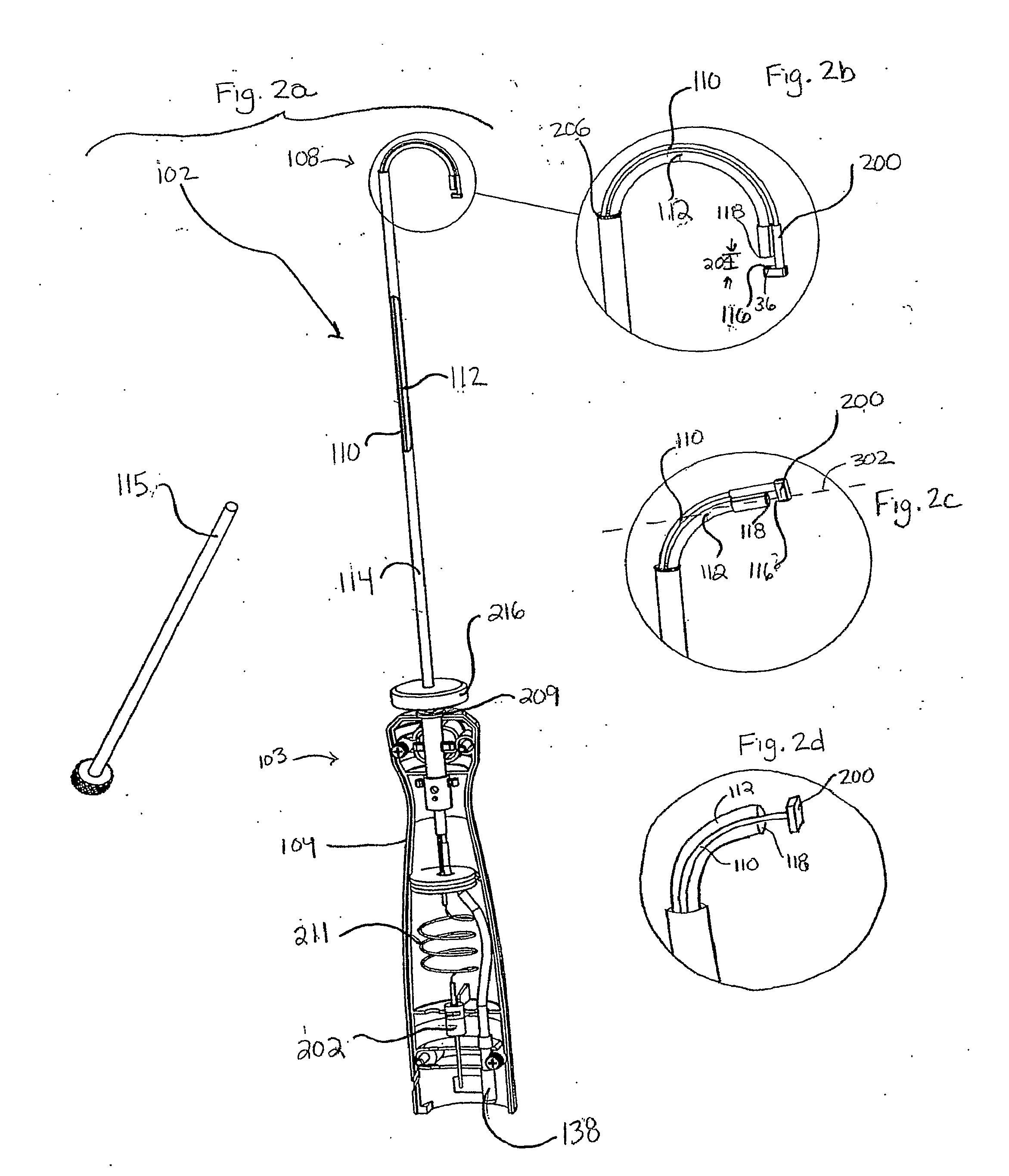
[0028]The present invention provides a variety of liquid jet instruments useful in a variety of applications, many of which instruments are especially well suited for a variety of surgical procedures. Certain embodiments of the liquid jet instruments provided by the invention can be configured in a variety of different ways for use in various surgical operating fields. Certain surgical instruments, according to the invention, are configured as surgical handpieces having a proximal end with a grasping region, or handle, shaped and configured to be comfortably held by the hand of an operator. The instruments may also have a distal end that includes at least one nozzle for forming a liquid jet. The distal end of certain embodiments of the inventive surgical instruments can be used to perform a surgical procedure on a patient. Although the liquid jet instruments described herein are shown as having a handpiece configuration, it should be understood that the invention is not strictly lim...


PUM


Abstract

The invention provides a variety of surgical instruments for forming a liquid jet, which are useful for performing a wide variety of surgical procedures. In some embodiments, the invention provides surgical liquid jet instruments having a pressure tube and an evacuation tube, where the pressure tube includes at least one nozzle for forming a liquid jet and where the evacuation tube includes a jet-receiving opening for receiving the liquid jet when the instrument is in operation. In some embodiments, the distal ends of both the pressure and evacuation tubes have a first configuration in a non-relaxed state and a second configuration in a more relaxed state. In some embodiments, a straightener is constructed to selectively control the configuration of the distal ends of both the pressure and evacuation tubes. The invention also provides surgical methods utilizing the inventive surgical liquid jet instruments for cutting or ablating a selected tissue within portions of a patient's spine, such as within the intervertebral disc.

Description

FIELD OF THE INVENTION[0001]The invention relates generally to surgical instruments for creating a liquid jet and methods for using the instruments in surgical procedures.BACKGROUND OF THE INVENTION[0002]There has been a trend in recent years to perform many surgical procedures using less invasive techniques by accessing surgical sites via small holes through the skin or through body orifices. These techniques are known as “minimally invasive surgery.” Minimally invasive surgical techniques commonly employed include endoscopic, laparoscopic, and arthroscopic surgical procedures. Minimally invasive surgical procedures are commonly preferred to open surgical procedures for many applications because the minimally invasive procedures induce less trauma to the patient during surgery and involve, in many cases, fewer potential complications and reduced recovery time.[0003]A variety of instruments have been developed and utilized for minimally invasive surgical procedures. Frequently used ...

Claims


Application Information

Patent Timeline
IPC IPC(8): A61B17/3203
CPCA61B17/3203A61B2017/2927A61B2017/00893A61B2017/003A61B17/92A61M3/00A61M11/02
Inventor BARRINGTON, JAMES E.STAID, KEVIN P.ELDRIDGE, DEREK BRUCE
Owner HYDROCISION
Why Eureka
Try Eureka