
Apparatus for drying hearing aids

a hearing aid and hearing aid technology, applied in drying, light and heating apparatus, furnace types, etc., can solve the problems of significant noise development, large motorized fans, damp hearing aids, etc., and achieve the effect of reducing the operating noise of the apparatus, increasing drying power, and increasing drying power

Inactive Publication Date: 2010-01-21
SIEMENS MEDICAL EQUIPMENT
View PDF13 Cites 15 Cited by
  • Summary
  • Abstract
  • Description
  • Claims
  • Application Information

AI Technical Summary

Benefits of technology

[0010]An electro-aerodynamic pump is embodied so as to generate gas ions and to accelerate the gas ions through an electrical field. This electro-aerodynamic operating principle can be realized with few electronic parts, basically only a voltage generator, an electrode pair for ionization and an electrode pair for accelerating air and / or gas atoms and molecules are needed. The small number of functional parts ensures high reliability.
[0011]The electro-aerodynamic pump does without moveable parts. This increases the reliability of the fan, since the mechanical sensitivity of moveable parts, e.g. rotating fan and associated bracket, is avoided. Furthermore, the avoidance of moveable parts also reduces the operating noises of the fan. The electro-aerodynamic pump does not generate any appreciable operating noise in comparison with the noise of the air flow generated. The pump operates not least very efficiently, so that a comparatively smaller installation size of the pump allows for comparatively strong air flows to be generated. As a result, a small space-saving fan is sufficient to generate an adequately strong air flow in order to dry hearing devices.
[0012]A further advantageous development of the invention provides for a supply air opening and a discharge air opening to be provided in the housing and for the interior of the apparatus to be molded such that an air flow generated by the fan is routed from the supply air opening through the hearing aid shell to the discharge air opening. This ensures that a hearing aid inserted for drying purposes is surrounded by a circulating air flow. At the same time, air, which has already absorbed moisture during the drying process, can escape through the discharge air opening and unused air can flow continuously through the supply air opening. The thus ensured inflow of unused, dry air renders a heater for additionally increasing the drying power unnecessary.
[0014]A further advantageous development of the invention provides for the supply air opening to be provided with a filter element, by means of which inflowing air is filtered and which has an air flow resistor, by means of which the air quantity flowing in is reduced by at least 25% per unit of time. On the one hand, the filter element prevents dirt particles, e.g. dust particles, from flowing in in significant quantities. On the other hand, the inflowing air flow can be restricted in terms of quantity and a higher circulating airflow can at the same time be maintained in the interior of the apparatus. The quantitative restriction of the inflowing air inevitably also restricts the quantity of the outflowing air and as a result reduces the operating noise of the apparatus. The significant air flow in the interior can at the same time achieve a greater drying power, as a result of which it is possible to dispense with an additional heater for increasing the drying power.
[0015]A further advantageous development of the invention provides for an additional embodiment as a charging station for charging rechargeable batteries in a hearing aid inserted into the hearing aid shell. As a result, the drying of the hearing aid, which is to take place regularly, can take place at the same time as and in collaboration with the recharging process which is likewise needed regularly. This improves user friendliness since separate user treatments are not needed for the two processes. In addition, the time required is reduced since the separate processes take place at the same time.

Problems solved by technology

Hearing aids become damp during wear, as a result in particular of sport activities and the effect of weather influences.
Motorized fans are however mostly relatively large and usually also have the disadvantage of significant noise development.
They are therefore not widespread in drying apparatuses for hearing aids.

Method used


Image

  • Apparatus for drying hearing aids

Examples


Embodiment Construction

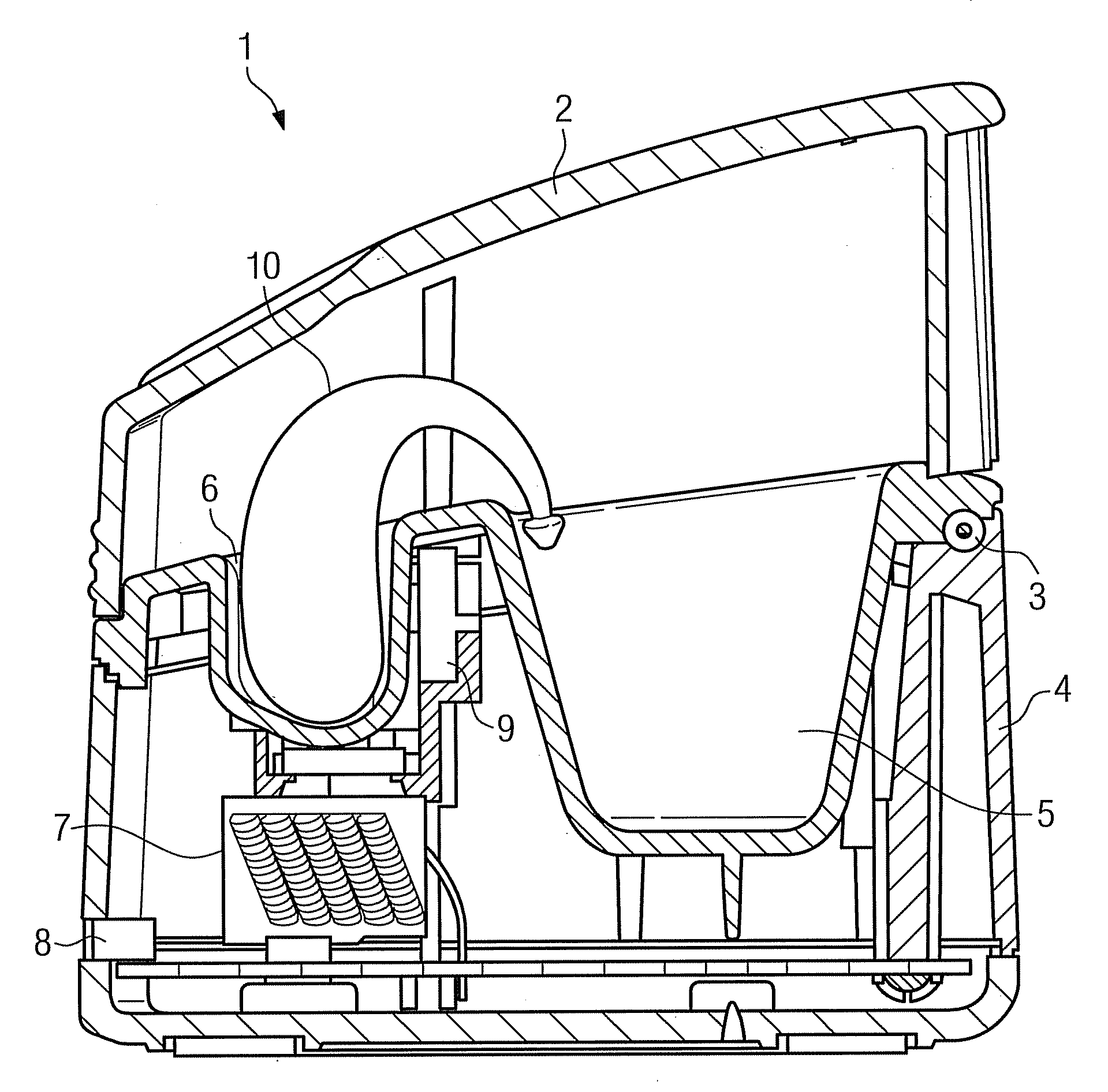
[0017]Figure shows a schematic sectional image of an apparatus 1 for drying a hearing aid. The apparatus includes a housing 4, which is closed by a cover which can be pivoted and / or swiveled about an axis 3. A molded part, into which a hearing aid shell 6 and an accessory shell 5 are countersunk, is located within the apparatus 1 and / or the housing 4. The hearing aid shell 6 is used for insertion of a hearing aid 10 for drying purposes. Accessories of the hearing aid, e.g. hearing tube or auditory canal inserts, can likewise be inserted into the accessory shell 5 for drying purposes.

[0018]In an advantageous embodiment, the apparatus 1 is not only used for drying but also for recharging rechargeable batteries in the hearing aid 10. In such a variant, corresponding charging contacts are provided in the hearing aid shell 6 as well as a charge current generator in the housing 4, which are however not shown in the drawing.

[0019]The apparatus 1 includes an electro-aerodynamic fan 7 as an ...


PUM


Abstract

The invention relates to an apparatus for drying hearing aids. According to the invention, the drying apparatus includes a housing and in the housing a hearing aid shell for inserting the hearing aid and a fan, with the fan accelerating air by means of an electro-aerodynamic pump. The electro-aerodynamic pump is advantageously embodied to generate gas ions and to accelerate the gas ions through an electrical field. The electro-aerodynamic fan is advantageous in that it requires little space and, except for the air flow, operates at a low noise level.

Description

CROSS REFERENCE TO RELATED APPLICATIONS[0001]This application claims priority of German application No. 10 2008 033 982.2 filed Jul. 21, 2008 and priority of German application No. 10 2008 047 220.4 filed Sep. 15, 2008, both of the applications are incorporated by reference herein in their entirety.FIELD OF THE INVENTION[0002]The invention relates to an apparatus for drying hearing aids.BACKGROUND OF THE INVENTION[0003]Hearing aids become damp during wear, as a result in particular of sport activities and the effect of weather influences. Hearing aids should be cleaned after use, whereby it is likewise possible for moisture to have an effect.[0004]The same applies to the wearable devices for treating tinnitus hearing damage which are comparable with hearing aids. Devices for tinnitus therapy, such as hearing aids, are therefore likewise to be understood below under the term “hearing aid”.[0005]To ensure an efficient operation over a lengthy period of time, hearing aids should be dri...

Claims


Application Information

Patent Timeline
IPC IPC(8): F26B3/02F26B21/00F26B25/06
CPCF26B9/003
Inventor HUSUNG, KUNIBERT
Owner SIEMENS MEDICAL EQUIPMENT
Learn More