Thin Film Solar Cell Having Photo-Luminescent Medium Coated Therein And Method For Fabricating The Same

Inactive Publication Date: 2010-01-21
NEXPOWER TECH
View PDF9 Cites 66 Cited by
  • Summary
  • Abstract
  • Description
  • Claims
  • Application Information

AI Technical Summary

Benefits of technology

[0007]A primary objective of the present invention is to provide a thin film solar cell having a photo-luminescent medium coated therein. When receiving the incident light, the photo-luminescent medium can be excited, and thus improving a spectrum sensibility of a photoconductive layer, and achieving an improved photoelectric conversion efficiency.
[0008]A further objective of the present invention is to provide a thin film solar cell having a photo-luminescent medium coated therein. The thin film solar cell is a substrate-type solar cell, in which the photo-luminescent medium is coated at an outer surface of a cover glass of the solar cell for improving a spectrum sensibility of a photoconductive layer.
[0009]Another objective of the present invention is to provide a thin film solar cell having a photo-luminescent medium coated therein. The thin film solar cell is a superstrate-type solar cell, in which the photo-luminescent medium is coated at an outer surface of a substrate of the solar cell for improving a spectrum sensibility of a photoconductive layer.
[0010]A furthermore objective of the present invention is to provide a thin film solar cell having a photo-luminescent medium coated therein. The thin film solar cell is a substrate-type solar cell, in which the photo-luminescent medium is coated at an inner surface of a cover glass of the solar cell for converting a visibl

Problems solved by technology

However, none of the selection and the coating processes of the fluorescent media employed by the aforementioned conventional solar cells has been optimized in accordance with the optimal light absorbing region of the photoconductive layer of the solar cell, as well as the characteristics of the substrate, the front electrode, and the window layer.
Furt

Method used


Image

  • Thin Film Solar Cell Having Photo-Luminescent Medium Coated Therein And Method For Fabricating The Same
  • Thin Film Solar Cell Having Photo-Luminescent Medium Coated Therein And Method For Fabricating The Same
  • Thin Film Solar Cell Having Photo-Luminescent Medium Coated Therein And Method For Fabricating The Same

Examples


Embodiment Construction

[0021]The accompanying drawings are included to provide a further understanding of the invention, and are incorporated in and constitute a part of this specification. The drawings illustrate embodiments of the invention and, together with the description, serve to explain the principles of the invention.

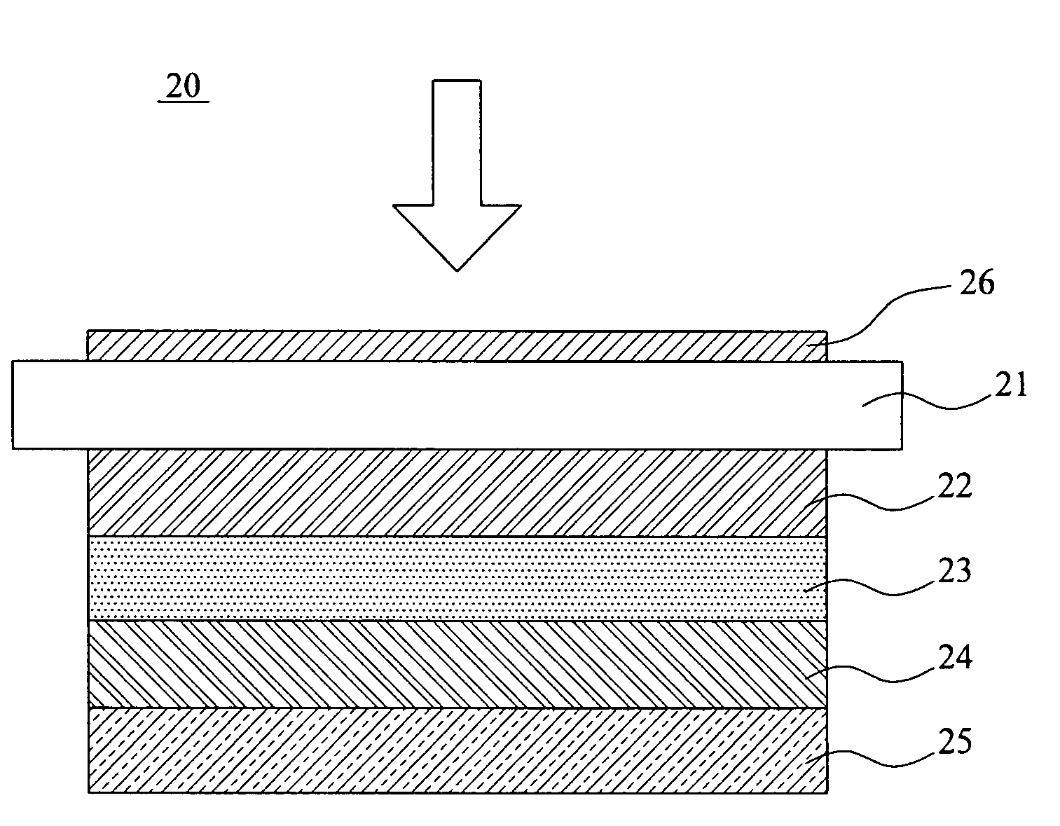
[0022]FIG. 2A is a cross-sectional view of a substrate-type solar cell having a photo-luminescent medium coated therein, according to a first embodiment of the present invention. As shown in FIG. 2A, the thin film solar cell 20 is substrate-type. The thin film solar cell 20 includes a transparent layer 21, a front electrode layer 22, a photoconductive layer 23, a back electrode layer 24, and a substrate 25, all of which are sequentially stacked in that order from a light incident surface of the thin film solar cell 20. The transparent layer 21 is a cover glass. The transparent layer 21 has an inner surface and an outer surface. The inner surface of the transparent layer 21 is in cont...


PUM


Abstract

A thin film solar cell having a photo-luminescent medium coated therein and a method for fabricating the same are provided. The thin film solar cell at least includes a transparent layer, a front electrode layer, a photoconductive layer, and a back electrode layer, which are sequentially stacked in that order from a light incident surface of the thin film solar cell. The transparent layer is a cover glass or a transparent substrate. The thin film solar cell further includes a photo-luminescent medium disposed on outer surface or inner surface of the transparent layer for absorbing the rest short wavelength light contained in the incident light and is then excited to emit a long wavelength light which can be effectively absorbed by the photoconductive layer. In such a way, the spectrum of the incident light is shifted, and thus an improved energy conversion efficiency is achieved.

Description

BACKGROUND OF THE INVENTION[0001]1. Field of the Invention[0002]The present invention relates generally to a thin film solar cell and a method for fabricating the same, and more particularly, to a thin film solar cell having a photo-luminescent medium coated therein and a method for fabricating the same.[0003]2. The Prior Arts[0004]Typically, for the purpose of improving the photoelectric conversion efficiency of a solar cell, a thin film of fluorescent substance is often coated on a glass substrate at a light receiving face of the solar cell. For example, JP Publication No. 2001-7377 (JP Application No. 11-215711) discloses a solar cell module 100. As shown in FIG. 1A, the solar cell module 100 includes a fluorescent coloring agent layer 101, a soda glass layer 102, an EVA filler layer 103, a solar cell 104 having an n+pp+polysilicon structure, and a back electrode sheet 105 sequentially stacked one on another from top to bottom. When absorbing a short wavelength light (<400 nm)...

Claims


Application Information

Patent Timeline
IPC IPC(8): H01L31/00B05D5/12
CPCH01L31/03921H01L31/055H01L31/0749Y02E10/52Y02E10/541Y02E10/548H01L31/075
Inventor YEH, CHIH-HUNG
Owner NEXPOWER TECH
Why Eureka
Try Eureka