Vehicle wet-type multi-plate brake device

a brake device and multi-plate technology, applied in the direction of hydraulic actuated brakes, mechanical devices, clutches, etc., can solve the problems of increasing the attachment space and the cost, affecting the driving experience, and affecting the operation of the brake device, so as to achieve the effect of reliably setting the predetermined distance, simple configuration, and reliable control of the piston stroke of the hydraulic piston

Active Publication Date: 2010-01-21
NIPPON YUSOKI
View PDF17 Cites 10 Cited by
  • Summary
  • Abstract
  • Description
  • Claims
  • Application Information

AI Technical Summary

Benefits of technology

[0016]Therefore, the present invention is contrived in consideration of the above-described problems, and an object of the invention is to provide a vehicle wet-type multi-plate brake device capable of realizing an automatic control mechanism having a simple configuration and constantly maintaining a piston stroke of a hydraulic piston, the mechanism being reliably operated. Accordingly, it is possible to provide the vehicle wet-type multi-plate brake device which prevents brake dragging at a starting time and prevents loss torque at a starting time, thereby reducing deterioration in fuel efficiency and improving a driving feeling.

Problems solved by technology

In such a wet-type multi-plate brake, when the mating plate or the friction plate is abraded, a piston stroke of the hydraulic piston is changed, thereby causing a problem in that a braking time or a non-braking time after a brake operation is changed, a driving feeling is deteriorated, and then a necessary oil quantity is increased.
However, in the method of controlling the supplied oil quantity, it is disadvantageous in that an attachment space and a cost increase largely due to an increase in size of a device.
Additionally, since there is a limitation in regulation amount in a stroke regulation using the piston seal, when the number of brake plates increases, a problem arises in that drag or the like occurs.
However, the automatic control mechanism for controlling the piston stroke of the hydraulic piston disclosed in Patent Document 1 (Japanese Patent Application Laid-Open No. 2000-304078) has the following problems to be solved.
However, since the return spring 012 urges the outer disk 03, urges the piston 04, and then urges the sleeve 08 via the piston 04, the initial position of the sleeve 08 is unstably determined upon returning the return spring 012, thereby causing a problem in that the stroke cannot be controlled with high precision.
Additionally, since the return spring 012 acts on the outer disk 03, when a return spring having a large spring constant is set in order to reliably return the piston 04, a force of the return spring increases with the abrasion states of the brake disks 02 and 03, thereby causing a problem in that a driving feeling is deteriorated.
Then, since an axial force of the sleeve 08 is controlled by the fitting state, it is difficult to carry out processing and assembling operations.
Also, when the abrasion occurs in age, a function is damaged.

Method used


Image

  • Vehicle wet-type multi-plate brake device
  • Vehicle wet-type multi-plate brake device
  • Vehicle wet-type multi-plate brake device

Examples


Embodiment Construction

[0037]Hereinafter, an embodiment of the invention will be described in detail with reference to the accompanying drawings. Here, although the dimension, the material, the shape, the relative arrangement, and the like of the component are described in the embodiment, the scope of the invention is not limited thereto so long as a particular description is not made, but those are only examples for a description.

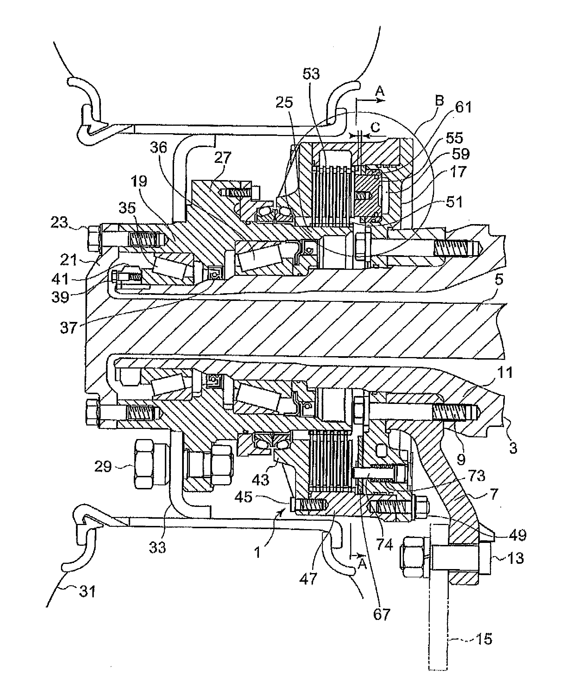
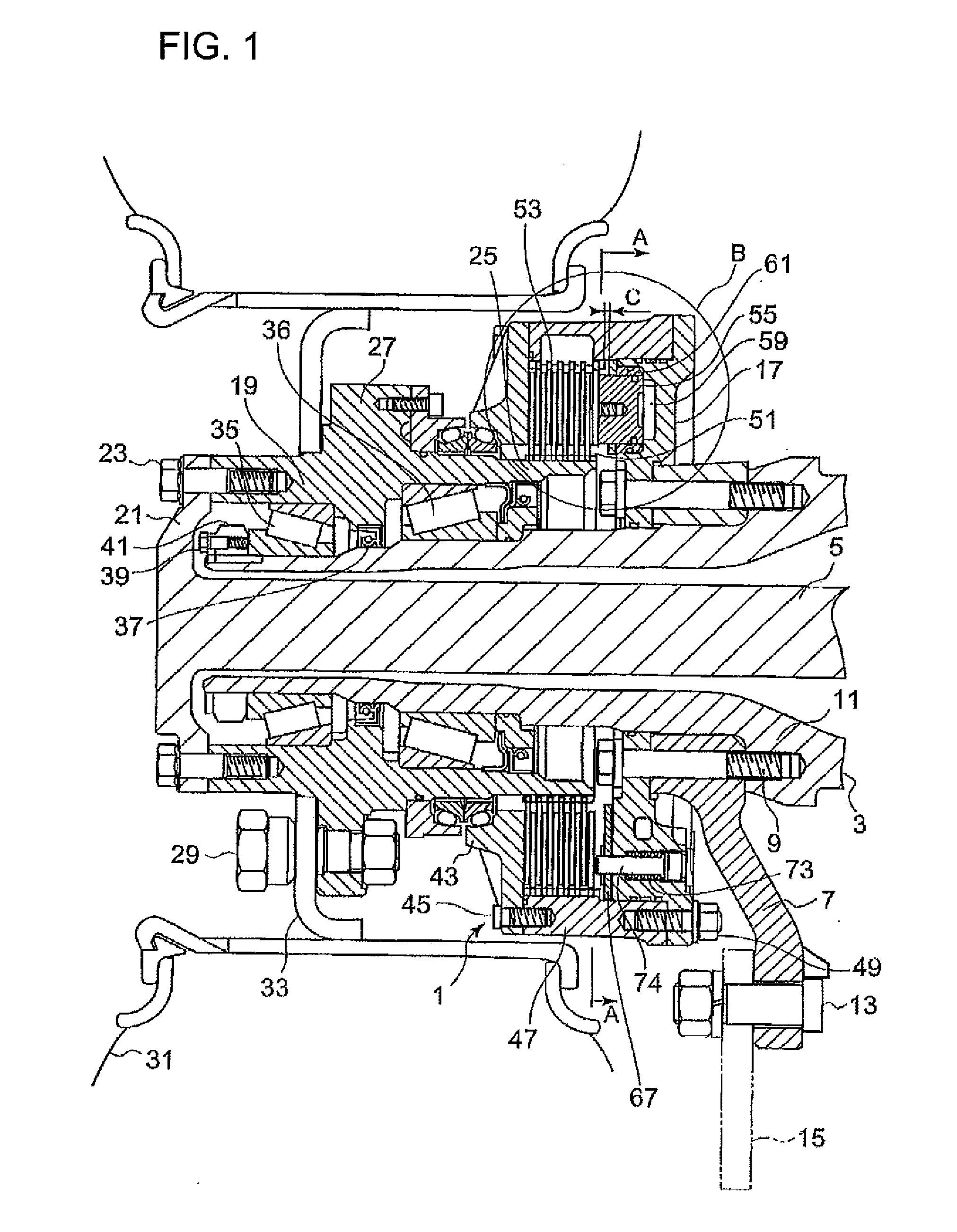
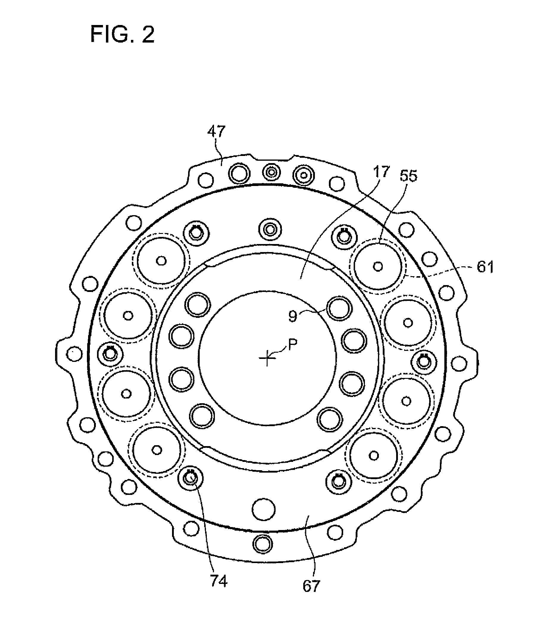
[0038]FIG. 1 is a longitudinal sectional diagram illustrating a structure of the wet-type multi-plate brake device according to the embodiment of the invention. FIG. 2 is a diagram taken along the arrow A-A shown in FIG. 1.

[0039]In FIGS. 1 and 2, a wet-type multi-plate brake 1 is provided between a vehicle body side and a wheel side, and an axle shaft 5 is inserted through a center portion of a vehicle-body-side axle housing 3.

[0040]An inner-peripheral side of a frame support 7 formed in an annular shape is fixed to a flange portion 11 of the axle housing 3 by the use of a plura...


PUM


Abstract

In a vehicle wet-type multi-plate brake device, an automatic control mechanism is provided which has a simple structure and constantly maintains a piston stroke of a hydraulic piston, the mechanism being reliably operated. A piston sleeve 61 is slidably provided between an inner-peripheral surface of a hydraulic piston hole 57 accommodating a hydraulic piston 55 and an outer-peripheral surface of the hydraulic piston 55, and has a sliding resistance so as to move together with the hydraulic piston 55. Additionally, a return plate 67 is disposed so as to be capable of coming into contact with only the piston sleeve 61 and of moving by a predetermined distance together with the piston sleeve 61. When a hydraulic pressure is supplied to an oil chamber 59, the hydraulic piston 55 and the piston sleeve 61 move together by a predetermined distance C against a returning force of the return plate 67, and then only the hydraulic piston 55 slides until coming into contact with a brake plate so that a positional relationship between the hydraulic piston 55 and the piston sleeve 61 is constantly maintained and a stroke of the hydraulic piston 55 is constantly maintained.

Description

TECHNICAL FIELD[0001]The present invention relates to a vehicle wet-type multi-plate brake device which is applicable to various vehicle brake devices including industrial vehicle brake devices and in which a mating plate attached to a frame support connected to an axle housing is configured to engage with or disengage from a friction plate attached to a brake hub connected to an axle shaft, and more particularly to, a vehicle wet-type multi-plate brake device provided with an automatic control mechanism for constantly maintaining a piston stroke of a hydraulic piston upon operating a brake.BACKGROUND ART[0002]Among brake devices used for wheeled industrial vehicles such as a forklift and a vehicle for a specialized operation, a wet-type multi-plate brake is widely used in which a mating plate is configured to engage with or disengage from a friction plate by the use of a hydraulic piston.[0003]In such a wet-type multi-plate brake, when the mating plate or the friction plate is abra...

Claims


Application Information

Patent Timeline
Patent Type & Authority Applications(United States)
IPC IPC(8): F16D65/54F16D65/18
CPCF16D65/54F16D55/40
Inventor SAKAHARA, TATSURO
Owner NIPPON YUSOKI
Why Eureka
Try Eureka