
Method for forming a high-gradient magnetic field and a substance separation device based thereon

a high-gradient magnetic field and separation device technology, applied in magnetic separation, separation process, filtration separation, etc., can solve the problem that the magnetic separator cannot be used for the separation of paramagnetic and diamagnetic substances and materials, and the practical impossibility of using this system for the separation of substances and materials, so as to increase the magnitude of the product bb and change the parameters of the magnetic field

Active Publication Date: 2010-01-21
GIAMAG TECH
View PDF11 Cites 15 Cited by
  • Summary
  • Abstract
  • Description
  • Claims
  • Application Information

AI Technical Summary

Benefits of technology

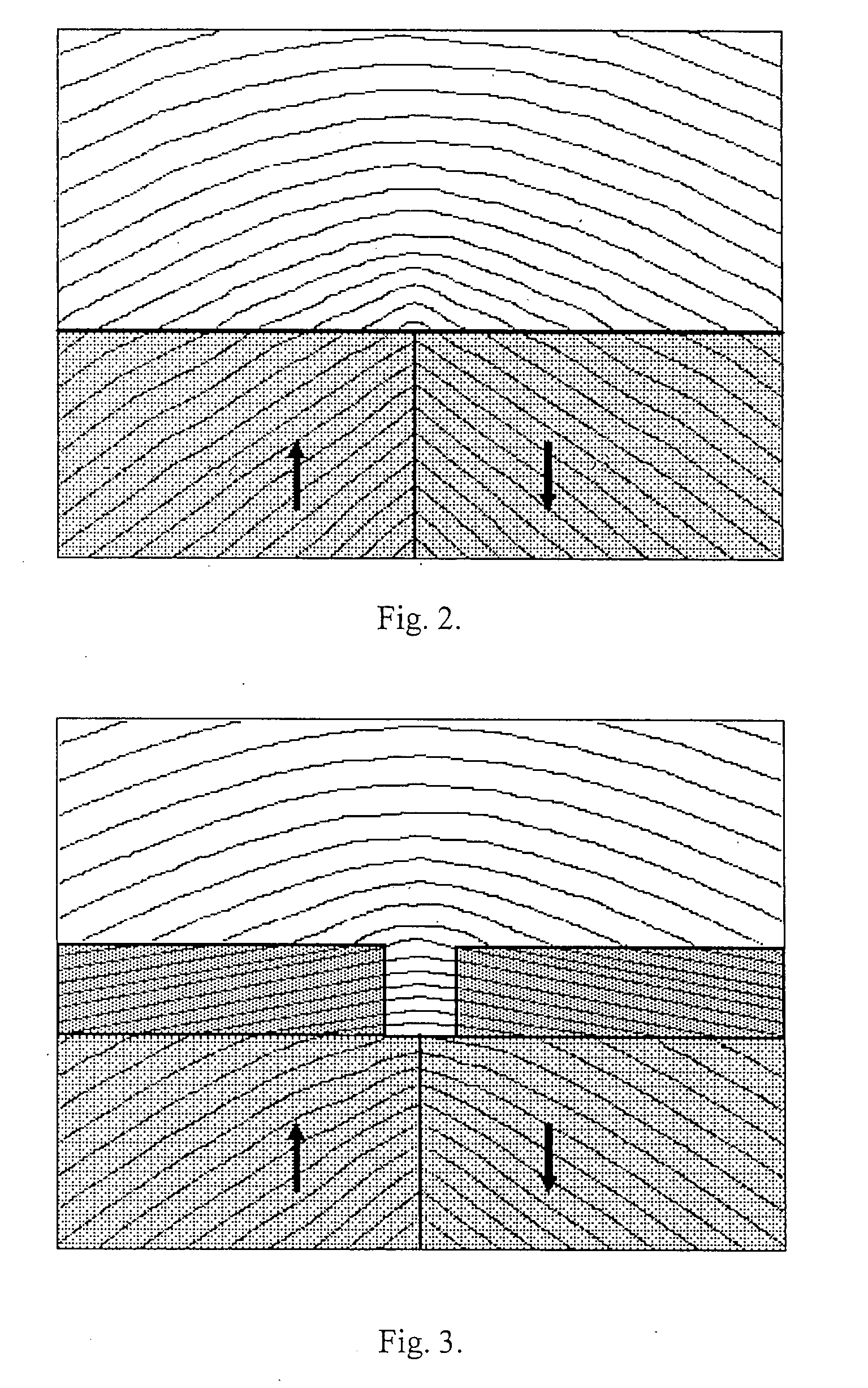
[0024]The main feature of the device according to the present invention is the ability to considerably increase the magnitude of the product B∇B in the zone of separation and also regulate the product B∇B, which gives the practical possibility of using the high magnetic stray fields for the creation of a high-sensitivity magnetic separator.
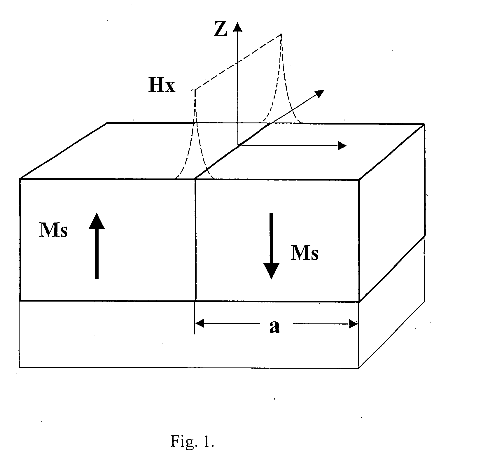
[0025]The illustrations in FIGS. 2 and 3, and also FIGS. 4 and 5, demonstrate the change in the magnetic field configuration compared to the known open domain structure [1], that is achieved due to the invention. The presented illustrations show that with the magnetic system according to the invention it is achieved not only a concentration of the magnetic field in the zone formed by the gap between the plates, but also a change in the shape of the magnetic force lines, as well as in the magnitude and distribution of the magnetic induction nearby the edges of the joined sides of the magnets. Thus, the invention makes it possible to change the parameters of the magnetic field considerably, and to create the most suitable conditions for the separation of materials over a wide range of their magnetic properties, including the separation of paramagnetic substances and materials in terms of the magnitudes of their paramagnetic susceptibility, and the separation of diamagnetic substances and materials in terms of the magnitudes of their diamagnetic susceptibility.

Problems solved by technology

However, this magnetic separator cannot be used for the separation of paramagnetic and diamagnetic substances and materials, because the values of the magnetic field parameters are not high enough.
The disadvantage of this magnetic system is the impossibility of controlling the form and gradient of the created magnetic fields which causes the practical impossibility of using this system for the separation of substances and materials.
The disadvantage of this separator is the necessity of introducing ferromagnetic bodies, (wires, balls, and the like) with a size of 25-60 μm into the substances being analyzed, this fact substantially limiting the possible range of properties and characteristics of the substances to be separated.
The disadvantage of this device is the necessity of introducing ferromagnetic bodies in the form of the filter, into the substances being analyzed and the impossibility of its application for the separation of non-liquid substances.
The disadvantage of this magnetic system is the impossibility of achieving such parameters of the magnetic field that would allow using it for the separation paramagnetic substances in terms of the magnitudes of their paramagnetic susceptibility.

Method used


Image

  • Method for forming a high-gradient magnetic field and a substance separation device based thereon
  • Method for forming a high-gradient magnetic field and a substance separation device based thereon
  • Method for forming a high-gradient magnetic field and a substance separation device based thereon

Examples


Embodiment Construction

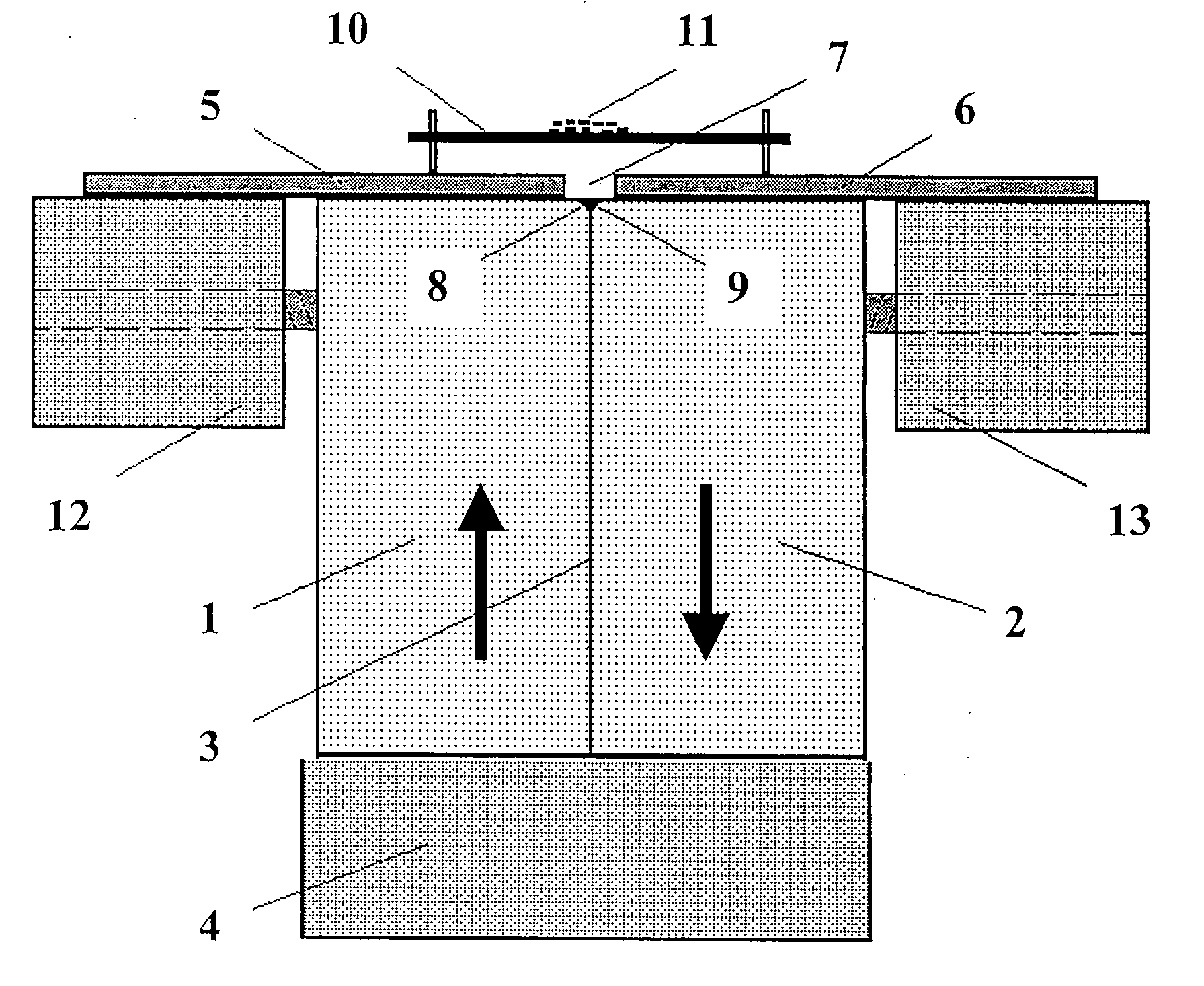
[0033]The disclosed device (see FIG. 6) consists of two magnets 1 and 2 of a predominantly rectangular shape, with opposite directions of magnetization (shown by arrows in the figure). The magnets are made of a material with a much greater magnetic anisotropy than the induction of a material of magnets, such as neodymium-iron-boron, ironplatinum or samarium-cobalt, for example.

[0034]In experiments sintered neodymium-iron-boron magnets were used with a remnant induction of about 1.3 T, an intrinsic coercive force of magnetization of about 1300 kA / m, and a maximum energy product of about 320 kJ / m3. The size of magnets was 25×50×50 mm.

[0035]The magnets 1 and 2 are joined together along a plane 3 and and their lower sides placed on a basis 4 in the form of a plate made of soft-iron material, for example, with a thickness of 5-25 mm.

[0036]On the upper sides of the magnets 1 and 2, thin plates 5 and 6 are located which are made of a magnetic soft material with high magnetic saturation ind...


PUM

PropertyMeasurementUnit
Thicknessaaaaaaaaaa
Widthaaaaaaaaaa
Polarityaaaaaaaaaa

Abstract

The invention relates to a magnetic separation device and is used for separating paramagnetic substances from diamagnetic substances, the paramagnetic substances according to the paramagnetic susceptibility thereof and the diamagnetic substances according to the diamagnetic susceptibility thereof. Said invention can be used for electronics, metallurgy and chemistry, for separating biological objects and for removing heavy metals and organic impurities from water, etc. The inventive device is based on a magnetic system of an open domain structure type and is embodied in the form of two substantially rectangular constant magnets (1, 2) which are mated by the side faces thereof, whose magnetic field polarities are oppositely directed and the magnetic anisotropy is greater than the magnetic induction of the materials thereof. Said magnets (1, 2) are mounted on a common base (4) comprising a plate which is made of a non-retentive material and mates with the lower faces of the magnets, thin plates (5, 6) which are made of a non-retentive material, are placed on the top faces of the magnets and forms a gap arranged above the top edges (8, 9) of the magnets (1, 2) mated faces. A nonmagnetic substrate (10) for separated material (11) is located above the gap (7).

Description

TECHNICAL FIELD [0001]The invention relates to methods and devices of magnetic separation and it is intended for: a) the separation of paramagnetic substances from diamagnetic ones, b) the division of paramagnetic substances depending on their paramagnetic susceptibility, and c) the division of diamagnetic substances depending on their diamagnetic susceptibility. Possible fields of application of the invention are production of clean and super pure substances and materials in electronics, metallurgy and chemistry, separation of biological subjects (red blood cells, “magnetic bacteria”, etc.) in biology and medicine, removal of heavy metals and organic impurities from water, etc.BACKGROUND ART [0002]The basic factor of magnetic separation is the magnetic force, which acts on a particle of the substance and which is proportional to the magnetic susceptibility of the substance, the value of the magnetic induction B and the value of the gradient ∇B of the applied magnetic field. Therefo...

Claims


Application Information

Patent Timeline
IPC IPC(8): B03C1/025B03C1/00
CPCB03C1/0332B03C1/22B03C2201/22B03C1/035Y10T29/4902B03C1/025
Inventor GLEBOV, VLADIMIR ALEXANDROVICHGLEBOV, ALEXEY VLADIMIROVICHILYASHENKO, EVGENY IVANOVICHSKJELTORP, ARNE TORBJORNJOHANSEN, TOM HENNING
Owner GIAMAG TECH
Learn More