Non-rectangular pixel array and display device having same

a display device and non-rectangular technology, applied in the field of non-rectangular pixel array and non-rectangular display device, to achieve the effect of excellent design property and functionality, high design property, and reduced irregular colors

Active Publication Date: 2010-01-21
NEC LCD TECH CORP
View PDF8 Cites 55 Cited by
  • Summary
  • Abstract
  • Description
  • Claims
  • Application Information

AI Technical Summary

Benefits of technology

[0030]With the above configuration, it is made possible to realize the oddly shaped (non-rectangular) pixel array and the display device having a smooth and gentle outer circumferential shape without sacrificing brightness, viewability, and fidelity of an image. Particularly, in the case of using a color pixel, the number of color pixels having a same color and being adjacent to one another in a line-like manner is not more than one and, therefore, irregular colors can be reduced and a smooth and gentle outer circumferential contour can be expressed. More specifically, by using the non-rectangular pixel array of the present invention, the display device being excellent in designing property and functionality can be achieved. For example, the display device, having a highly designing property, with an outer shape being approximately similar to the outer circumferential shape of the pixel array can be realized. In particular, when a color pixel is used, the number of color pixels having a same color and being adjacent to one another in a line-like manner is not more than one and, therefore, it is possible to realize display device having an outer shape being approximately similar to an outer circumferential shape of the pixel array.
[0031]Further, in the another configuration of the present invention, the non-rectangular pixel functions as a plurality of kinds of sub-pixels...

Problems solved by technology

However, as described above, the conventional display devices stated in the Patent References 1 and 2 have disadvantages that, though the display area (pixel arrays 40 and 48) is non-rectangular, each rectangular pixel 47 making up the display area is rectangular and, therefore, a region occurs in which no matching between the rectangular pixel 47 and non-rectangular outer circumferential contour is realized.
. . is arranged in a stepwise manner and, as a result, the display area having a smooth and gentle contour shape cannot be obtained, which gives uncomfortable jaggies to viewers, causing a loss of attractive appearance and unfavorable designing.
Also, the display devices disclosed in the Patent References 1 and 2 have another problem in that, when a given slant line or curved pattern including an outer circumferential contour of a shape is to be displayed, more specifically, an equal distance line pattern (due to mimicking of a contour line on a map, such a pattern is referenced to as a contour line like shape or figure) obtained by performing linking between positions, by a specific equal distance, far from a pattern similar to an outer circumference of a display area or from an outer circumferential contour or the like is to be displayed, since a plurality of rectangular pixels is selected and controlled in a stepwise manner, as shown in FIG. 48, a slant figure or curved FIG. 55a is visually recognized by a viewer as the pattern having uncomfortable jaggies and distortion, which is not preferable in terms of display quality.
In addition, the color display device having the rectangular display area (in the example, display area having the same as in FIG. 48) shown in FIG. 49 also has a problem in that a region occurs in which a specified color only is enhanced in an outer circumferential curved portion of a display area or in an outer shape line portion of a display pattern, which is recognized as irregular color or a like.
However, a problem arises that, by displaying in white with the priority given to a hue, irregular colors disappear, while a corner occurs in three color pixels and jaggies increase in the display area and display pattern which, in this case, are uncomfortable.
In addition, another problem arises that, the display device having an extremely odd shape in which a hollow portion or through hole exists in the display area, out of the non-rectangular display devices, can not be realized by configurations disclosed in the Patent References 1 and 2.
Further, the display device stated in the Patent Reference 2 also has a disadvantage in that, as shown in FIG. 46, each of the first address designating conductors 49, 49, .
. . resulting in partial blocking of the aperture, thus causing a decrease in an aperture rate.
The display device still further has a disadvantage that the positions in which the first address designating conductors 49, 49, .
. . differ for every rectangular pixel 47 and, as a result, an arrangement of the switching elements mounted in a one to one relationship at the ...

Method used


Image

  • Non-rectangular pixel array and display device having same
  • Non-rectangular pixel array and display device having same
  • Non-rectangular pixel array and display device having same

Examples


first exemplary embodiment

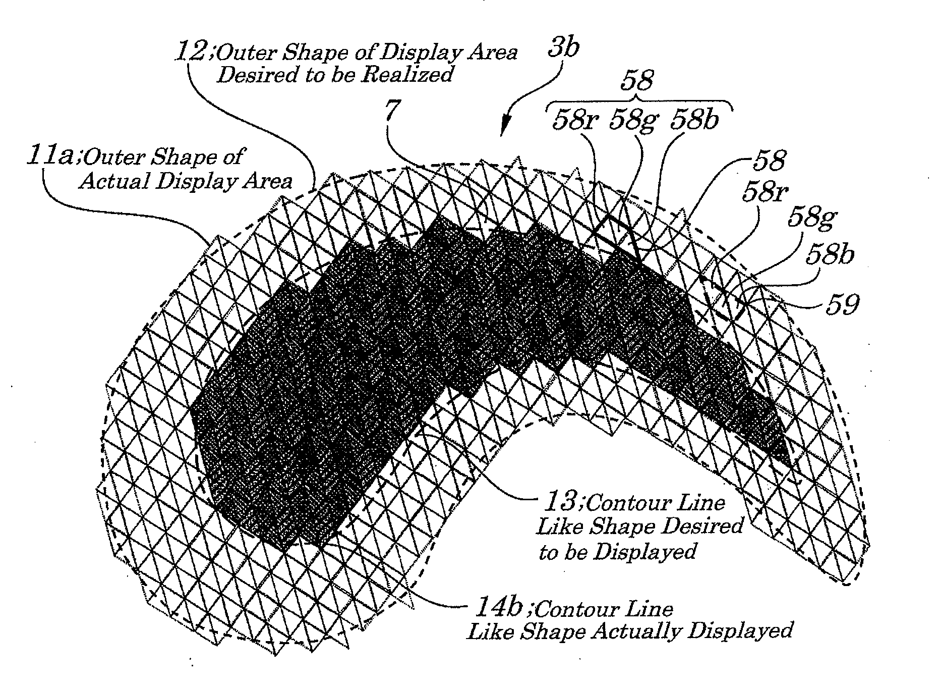
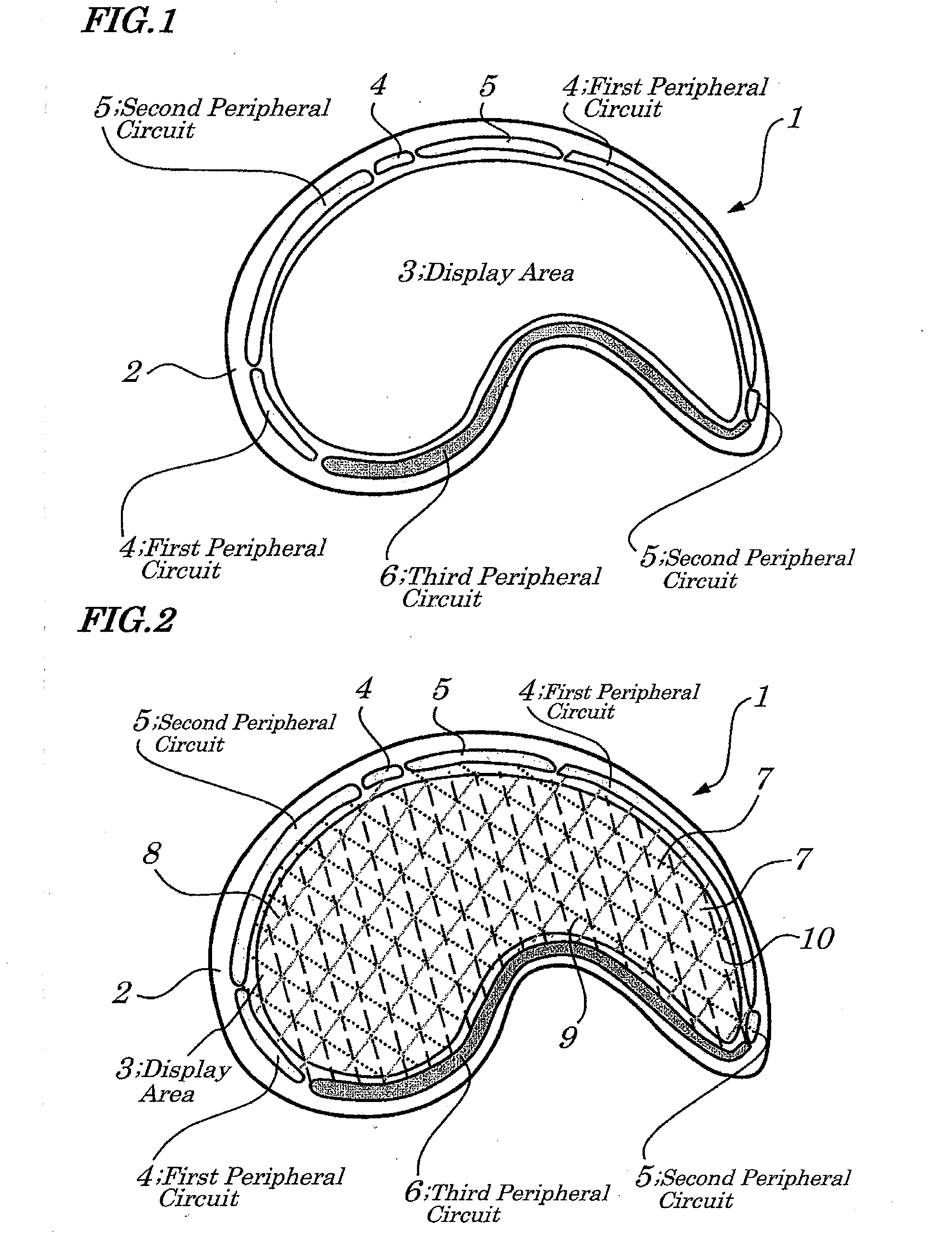
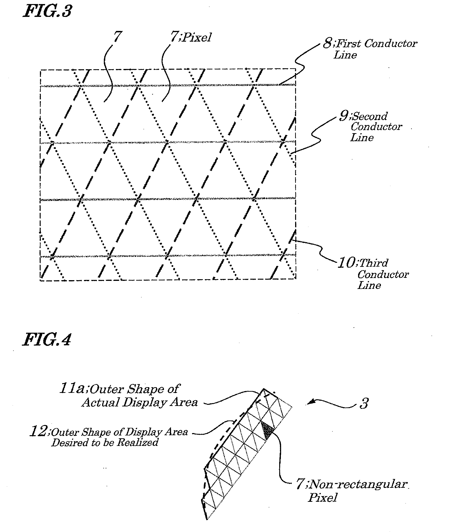
[0089]Hereinafter, the first exemplary embodiment of the present invention is described by referring to drawings. FIG. 1 is a front view diagrammatically showing a configuration of a non-rectangular display device according to the first exemplary embodiment. FIG. 2 is a front view diagrammatically showing pixels in a display area and wiring patterns of various types making up the display device of FIG. 1. FIG. 3 is an enlarged view schematically showing one part of the display area of FIG. 2. FIG. 4 is an enlarged view schematically showing, in a partially enlarged manner, an outer circumferential portion of the display area of FIG. 2. The display device 1 of the first exemplary embodiment, as shown in FIGS. 1 and 2, is a non-rectangular display device, an outer portion of which has a comma-shaped-bead-like shape (MAGATAMA) and is mainly made up of a comma-shaped-bead-like substrate 2, a display area (pixel area) 3 having a comma-shaped-bead-like shape being an almost same shape (si...

example 1

[0104]FIG. 8 is a diagram schematically and partially showing electrical configurations of a display area of a first example of the first exemplary embodiment. The display area of the example 1, as shown in FIG. 8, is configured so that many first conductor line groups made up of a plurality of row conductor lines 8a, 8a, . . . arranged in parallel to each other along a first direction with a specified interval therebetween, many second conductor line groups made up of a plurality of first column conductor lines 9a, 9a, . . . arranged in parallel to each other along a second direction with a specified interval therebetween, and many third conductor line groups made up of a plurality of second column conductor lines 10a, 10a, . . . arranged in parallel to each other along a third direction with a specified interval therebetween, are arranged on a substrate and each of the row conductor lines 8a, first column conductor lines 9a, second column conductor lines 10a is connected to each o...

example 2

[0108]FIG. 9 a diagram schematically and partially showing electrical configurations of a display area according to a second example of the first exemplary embodiment. The display area of the second example of the first exemplary embodiment, as shown in FIG. 9, is configured so that many first conductor line groups made up of a plurality of gate lines 16, 16, . . . arranged in parallel to each other along a first direction with a specified interval therebetween, many second conductor line groups made up of a plurality of data lines 17, 17, . . . arranged in parallel to each other along a second direction with a specified interval therebetween, and many third conductor line groups made up of a plurality of storage capacitance lines 18, 18, . . . arranged in parallel to each other along a third direction with a specified interval therebetween, are arranged on a substrate and each of the gate lines 16, data lines 17, storage capacitance lines 18 is connected to each of active elements ...


PUM


Abstract

There is provided a display area made up of a pixel array with a non-rectangular shaped outer circumference and the pixel array is made up of a plurality of non-rectangular pixels wherein a first conductor line group including a plurality of first conductor lines and a second conductor line group including a plurality of second conductor lines, and a third conductor line group including a plurality of third conductor lines are arranged so as to intersect with one another. Thus, without sacrificing brightness, viewability, and fidelity of an image, pixel array (display device) with the non-rectangular outer circumferential shape being excellent in design characteristics is realized.

Description

INCORPORATION BY REFERENCE[0001]This application is based upon and claims the benefit of priorities from Japanese Patent Application No. 2008-124113, filed on May 11, 2008 and Japanese Patent Application No. 2009-114790, filed on May 11, 2009, the disclosures of which are incorporated herein in its entirely by reference.BACKGROUND OF THE INVENTION[0002]1. Field of the Invention[0003]The present invention relates to a non-rectangular pixel array and a non-rectangular display device made up of the pixel array and more particularly to the pixel array having a non-rectangular outer circumferential shape and the non-rectangular display device made up of the pixel array with outer circumferential portion of which has a shape of a smoothly curved line.[0004]2. Description of the Related Art[0005]In recent years, due to extension of applications associated with progress of miniaturization, thinning, light-weighting of a display device, demands for commercialization of such a display device ...

Claims


Application Information

Patent Timeline
IPC IPC(8): G09G5/00
CPCG02F1/134336G02F1/13452G06F3/14G09G3/20H05B37/00G09G2300/0439G09G2300/0842G09G2320/02G09G2340/0457G09G5/00G02F2201/56H05B47/19H05B47/16Y02B20/40
Inventor TAKATORI, KENICHI
Owner NEC LCD TECH CORP
Why Eureka
Try Eureka