
Systems and methods for highly efficient video compression using selective retention of relevant visual detail

a video and detail retention technology, applied in the field of digital video signals, can solve the problems of video distortion, increased bandwidth control, and reduced overall memory required to store such movie files, and achieve the effects of improving compression efficiency, high perceptual quality of decompressed video, and improving bandwidth control

Inactive Publication Date: 2010-01-21
WORLDPLAY BARBADOS
View PDF12 Cites 4 Cited by
  • Summary
  • Abstract
  • Description
  • Claims
  • Application Information

AI Technical Summary

Benefits of technology

[0019]Systems and methods are presented for compressing digital video signals in a manner that minimizes and can even prevent the creation of block artifacts and improves compression efficiency using the selective removal of data representing visually imperceptible or irrelevant detail. Bandwidth control is improved through prioritized removal of data exceeding permissible bandwidth limits. This provides a process by which a coupled compressor and de-compressor system can effect the transmission or storage of video at low bitrates with high perceptual quality of the decompressed video.
[0020]In one embodiment, the concepts discussed in the above-identified co-pending patent applications entitled SYSTEMS AND METHODS FOR IMPROVING THE QUALITY OF COMPRESSED VIDEO SIGNALS BY SMOOTHING BLOCK ARTIFACTS and SYSTEMS AND METHODS FOR IMPROVING THE QUALITY OF COMPRESSED VIDEO SIGNALS BY SMOOTHING THE ENTIRE FRAME AND OVERLAYING PRESERVED DETAIL may be used in combination with the concepts discussed herein to reduce the required bandwidth for transmission of the ‘Carrier’ video stream. The compression / decompression process described herein takes advantage of features of the HVS which allow significant bitrate savings to be achieved for a given perceptual quality of the decompressed video.
[0021]One important observation is that the HVS is relatively fast at perceiving the overall structure and motion of objects, but is slower to ‘focus in’ on fine detail. For example, a baseball batter can perceive the motion of a pitcher and ball sufficiently quickly to initiate an appropriate reaction and hit the ball with reasonable reliability, but will have little or no perception of the fine details of the threads or scuff-marks on the ball as it moves and spins in its flight. On the other hand, if that ball were stationary and placed a few feet away from the batter, he / she could perceive and describe these details quite precisely. Advantage is taken of this characteristic of the HVS by suppressing the appearance of such imperceptible detail as the threads on a fast-spinning ball so that it does not consume bandwidth in the compressed video representation.
[0022]In addition to the reaction rate characteristics described above, other HVS characteristics may be leveraged to increase compression efficiency. For a given bandwidth, perceived video quality may be optimized by prioritizing the transmission of the ‘most relevant’ details in a video sequence. So, for example, stationary or slow-moving details will generally have higher priority than fast-moving details. Similarly, for most types of video the details near the centre of the video may be more ‘relevant’ to the viewer than details around the periphery of the image. Bandwidth may be utilized accordingly to convey the central details with greater fidelity than the peripheral details.
[0025]In contrast to wavelet methods, this method achieves lower bandwidths, in part, due to its capability to selectively suppress detail and productively use motion estimation and compensation to achieve excellent compression for high-motion scenes.

Problems solved by technology

The Internet provides an especially complex example of the delivery of video data in which video files are multiplexed in many different ways and over many different channels (i.e. paths) during their downloaded transmission from the centralized server to the end user.
Compression of the video component of these video files therefore not only conserves bandwidth, for the purposes of transmission, but it also reduces the overall memory required to store such movie files.
That is, video distortion tends to increase with increasing levels of compression.
As the level of video compression is increased, the video distortion eventually becomes visible to the HVS and eventually this distortion becomes visibly-objectionable to the typical viewer of the real-time video on the chosen display device.
In such cases, by far the most visibly-objectionable artifact is the appearance of artifact blocks in the displayed video scene.
The problem of attenuating the appearance of visibly-objectionable artifacts is especially difficult for the widely-occurring case where the video data has been previously compressed and decompressed, perhaps more than once, or where it has been previously re-sized, re-formatted or color re-mixed.
In such cases, a priori knowledge of the locations of the artifact blocks is almost certainly unknown and therefore methods that depend on this knowledge do not work.
This constraint is a major design challenge.
For DCT-based and other block-based compression methods, the most serious visibly-objectionable artifacts are in the form of small rectangular blocks that typically vary with time, size and orientation in ways that depend on the local spatial-temporal characteristics of the video scene.
As the level of compression increases, and in its goal to retain the above mentioned fidelity, the compression method (in the so-called encoder) eventually allocates a constant (or near constant) intensity to each block and it is this block-artifact that is usually the most visually objectionable.
It is estimated that if artifact blocks differ in relative uniform intensity by greater than 3% from that of their immediately neighboring blocks, then the spatial region containing these blocks is visibly-objectionable.

Method used


Image

  • Systems and methods for highly efficient video compression using selective retention of relevant visual detail
  • Systems and methods for highly efficient video compression using selective retention of relevant visual detail
  • Systems and methods for highly efficient video compression using selective retention of relevant visual detail

Examples


Embodiment Construction

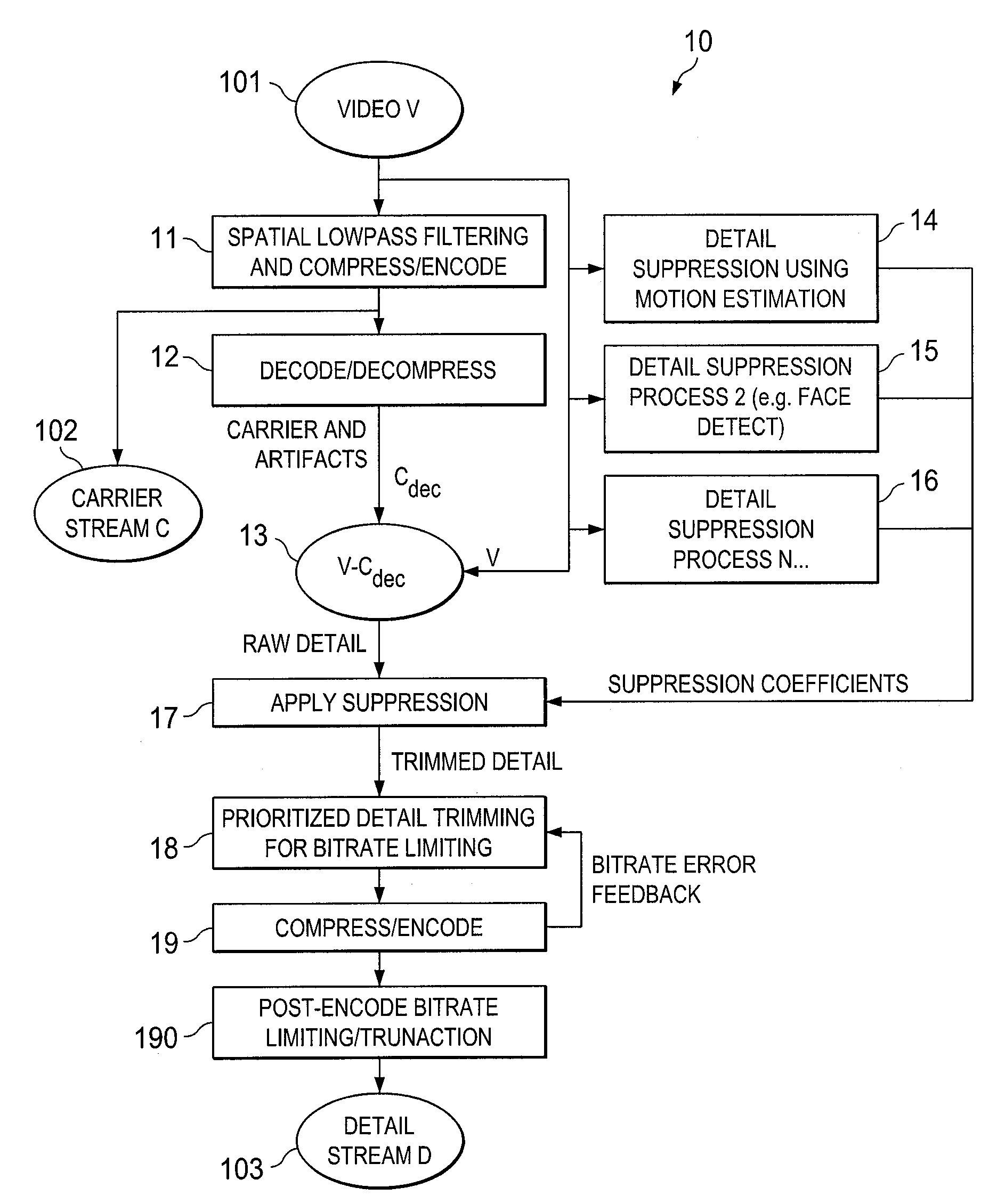
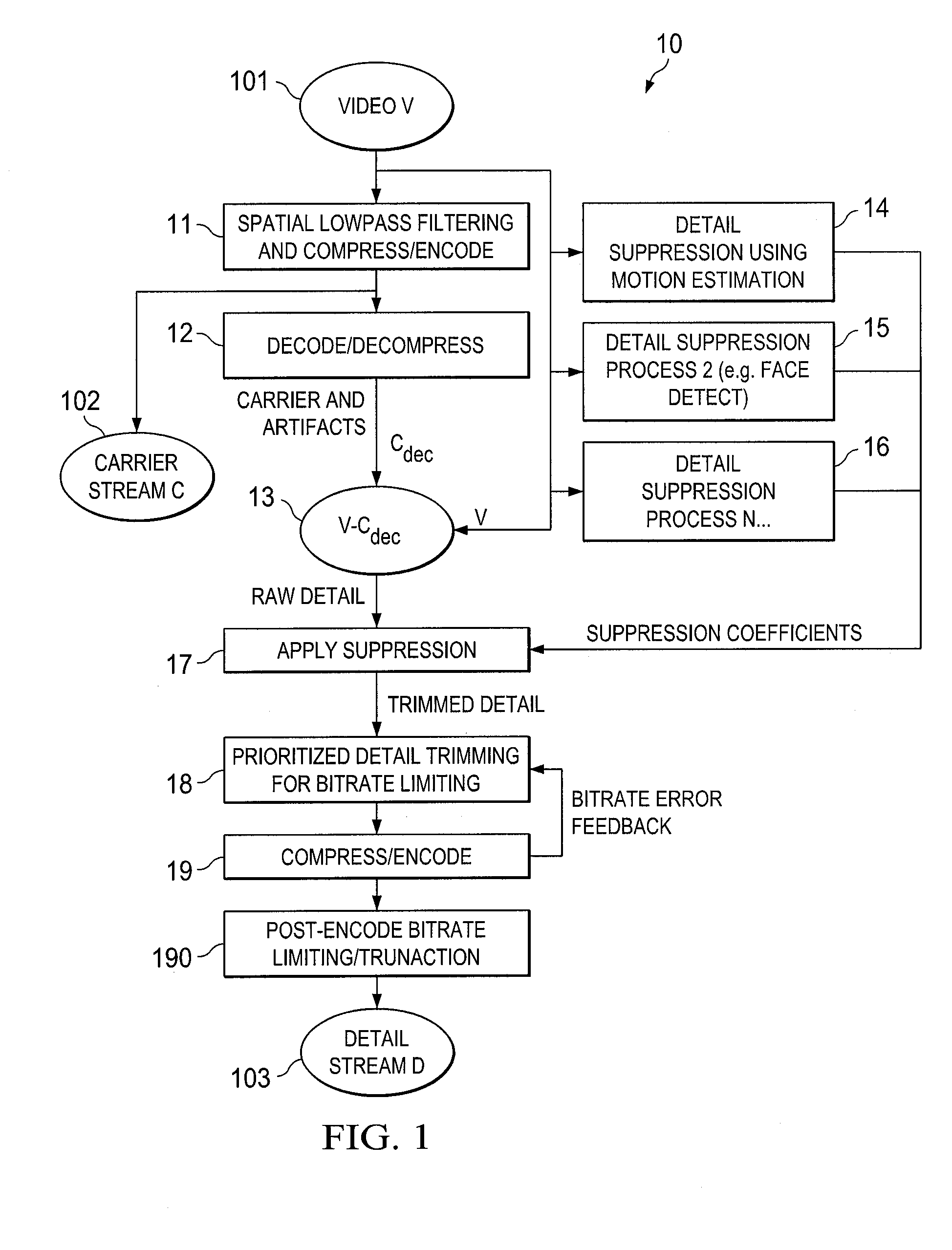
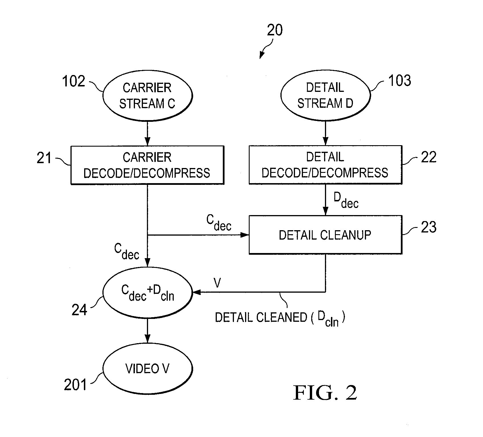
[0031]FIG. 1 shows one embodiment 10 of a method for encoding / compressing video frames according to the concepts discussed herein. This method can be used, by way of example, in system 30 shown in FIG. 3. Methods 10 and 20 can be, for example, software running in processors 32-1, 34-1, respectively. Also, the methods can be in firmware or ASICs if desired.

[0032]FIG. 1 illustrates an embodiment of a compression process which realizes the advantages described above, and which achieves important goals of an effective video transmission or storage system, including the use of very low bitrates for a given perceptual quality while maintaining a satisfactory image quality in low-bandwidth scenarios, The system has the capability of supporting precise single-pass control of compressed video stream bitrates while having robust handling of ‘difficult’ scenes such as high-motion, variable-motion, or chaotic video with a minimum of objectionable or distracting artifacts. The output of the comp...


PUM


Abstract

Systems and methods are presented for compressing digital video signals in a manner that prevents the creation of block artifacts and improves compression efficiency by the selective removal of data representing visually imperceptible or irrelevant detail. Bandwidth control is improved through prioritized removal of data exceeding permissible bandwidth limits. This provides a process by which a coupled compressor and de-compressor system can effect the transmission or storage of video at low bitrates with high perceptual quality of the decompressed video. In one embodiment, the low frequency components are removed from a video stream and either stored or transmitted in compressed format separate from the storage or transmission of the high frequency components of the video stream. Certain high frequency video stream details can be suppressed to further reduce bitrate.

Description

CROSS-REFERENCE TO RELATED APPLICATIONS[0001]This application is related to concurrently filed, co-pending, commonly owned patent applications SYSTEMS AND METHODS FOR IMPROVING THE QUALITY OF COMPRESSED VIDEO SIGNALS BY SMOOTHING BLOCK ARTIFACTS, U.S. patent application Ser. No. ______, Attorney Docket No. 54729 / P010US / 10806075; and SYSTEMS AND METHODS FOR IMPROVING THE QUALITY OF COMPRESSED VIDEO SIGNALS BY SMOOTHING THE ENTIRE FRAME AND OVERLAYING PRESERVED DETAIL, U.S. patent application Ser. No. ______, Attorney Docket No. 54729 / P011US / 10808778, which applications are hereby incorporated by reference herein.TECHNICAL FIELD[0002]This disclosure relates to digital video signals and more specifically to systems and methods for improving the quality of compressed digital video signals by taking advantage of features of the human vision system (HVS) which allow significant bitrate savings to be achieved for a given perceptual quality of the decompressed video.BACKGROUND OF THE INVENT...

Claims


Application Information

Patent Timeline
IPC IPC(8): H04B1/66
CPCH04N19/51H04N19/37H04N19/86H04N19/80H04N19/117H04N19/184H04N19/60
Inventor LANCASTER, GREGSHERWOOD, MATTBRUTON, LEONARD T.LOWE, DANNY D.
Owner WORLDPLAY BARBADOS
Learn More