
Pipe layer having swing speed adjustable system

Inactive Publication Date: 2010-01-28
VOLVO CONSTR EQUIP
View PDF2 Cites 4 Cited by
  • Summary
  • Abstract
  • Description
  • Claims
  • Application Information

AI Technical Summary

Benefits of technology

[0017]Embodiments of the present invention relate to a pipe layer having a swing speed adjustable system, which can variably adjust the amount of hydraulic fluid being supplied to a swing motor, and thus can optionally control the maximum swing speed in accordance with the use purpose of an excavator or a pipe layer, that can be effected through replacement of attachments in accordance with work conditions.
[0018]Embodiments of the present invention relate to a pipe layer having a swing speed adjustable system, which can heighten the swing speed to improve the work efficiency when it is used as an excavator, and which can reduce the maximum swing speed to secure the safety when it is used as a pipe layer having inherent functions (e.g. traveling, swing, and the like) of the excavator.
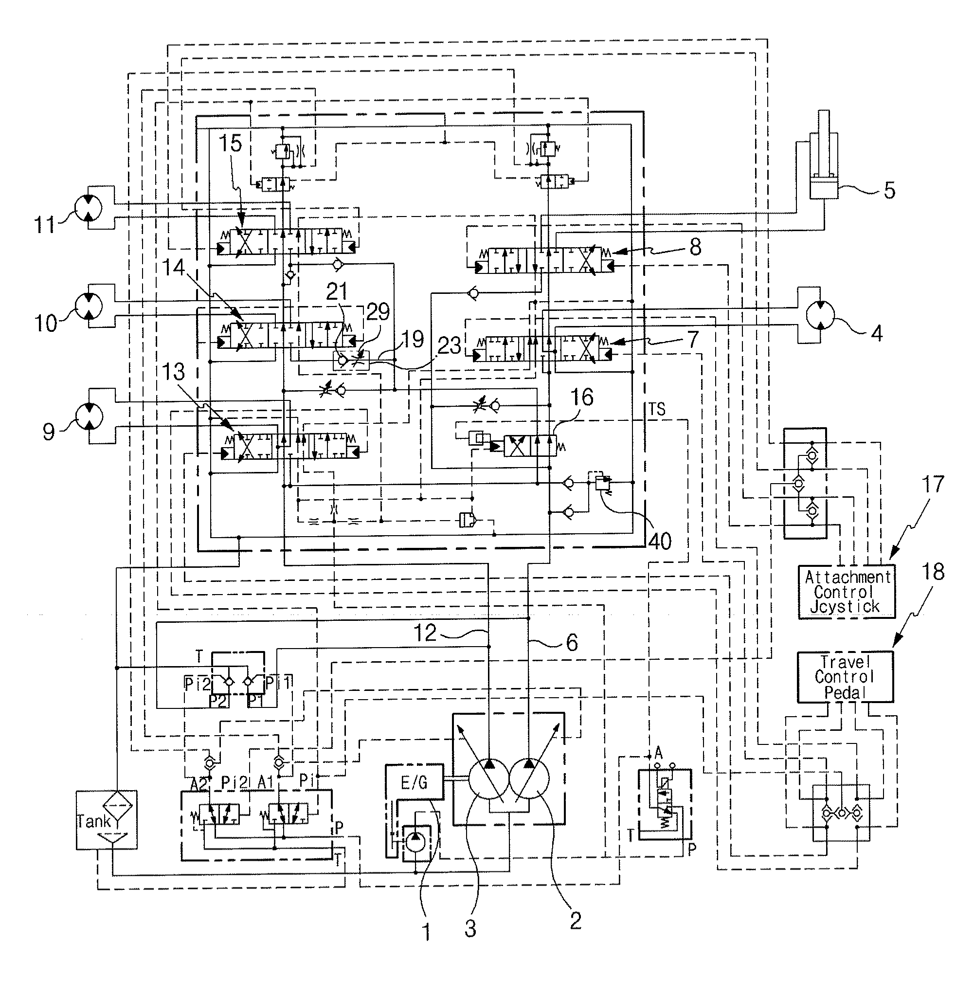
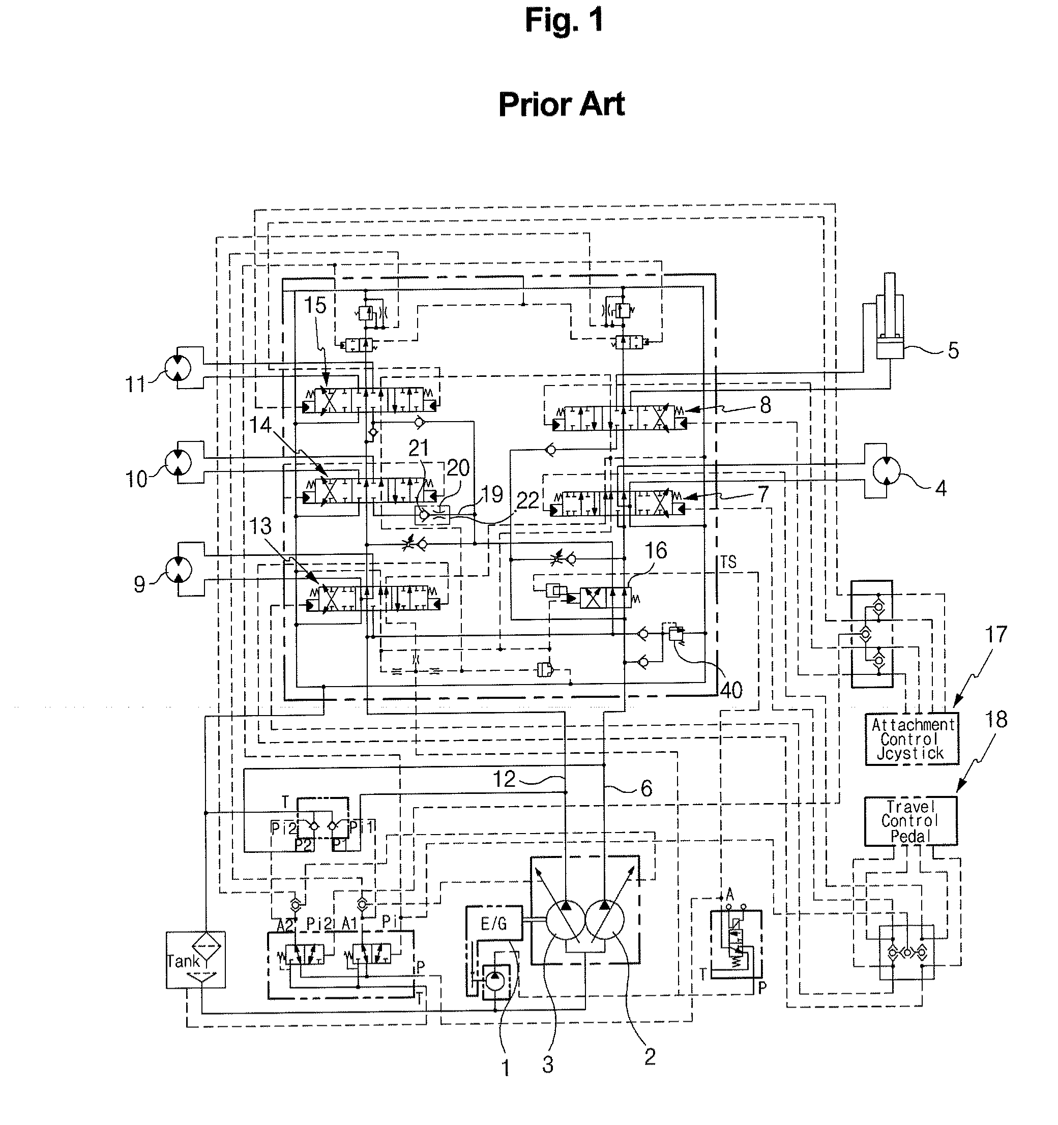
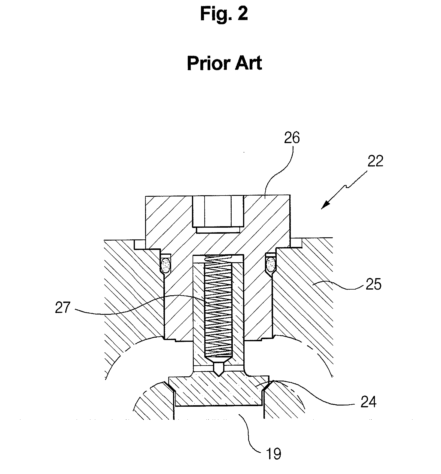
[0019]In one aspect of the present invention, there is provided a pipe layer having a swing speed adjustable system, which includes first and second variable displacement hydraulic pumps connected to an engine; a left traveling motor and a boom cylinder connected to the first hydraulic pump; control valves installed in a center bypass path of the first hydraulic pump, and shifted to control the flow direction and flow amount of hydraulic fluid being supplied to the left traveling motor and the boom cylinder; a right traveling motor, a swing motor, and a winch motor connected to the second hydraulic pump; control valves installed in a center bypass path of the second hydraulic pump, and shifted to control the flow direction and flow amount of hydraulic fluid being supplied to the right traveling motor, the swing motor, and the winch motor; a straight traveling valve installed on an upstream side of the center bypass passage of the first hydraulic pump, and shifted, in response to a signal pressure applied from an outside in a work mode for simultaneously driving a working device and a traveling device, to supply the hydraulic fluid fed from the first hydraulic pump to the boom cylinder, the swing motor, and the winch motor, and to supply the hydraulic fluid fed from the second hydraulic pump to the left and right traveling motors, respectively; and a variable load-hold check valve installed in an inlet-side flow path of the swing motor control valve to variably adjust a stroke of a poppet so that the amount of hydraulic fluid being supplied to the swing motor can be variably adjusted.
[0021]With the above-described construction, the pipe layer having a swing speed adjustable system according to embodiments of the present invention has the following advantages.
[0022]The pipe layer can variably adjust the amount of hydraulic fluid being supplied to a swing motor, and thus can optionally control the maximum swing speed in accordance with the use purpose of an excavator or a pipe layer, which can be effected through replacement of attachments in accordance with work conditions.
[0023]Also, the pipe layer can improve the work efficiency due to the quick swing speed of an upper frame when it is used as an excavator, and can minimize shaking of an oil pipe, which is pulled and carried by a wire rope, through reduction of the maximum swing speed to secure the safety when it is used as a pipe layer.

Problems solved by technology

However, if shaking of the oil pipe occurs due to the uneven ground or the operator's unskilled manipulation of the equipment while the crane is moved in a state where the oil pipe is pulled up using a flexible wire rope wound on a winch of the crane, collision may occur between the oil pipe and a part of the equipment to damage the equipment and the oil pipe.
Also, if the center of gravity is lost due to the shaking of the oil pipe and so on, the oil pipe may secede from the rope to cause the injury of the operator and the damage of goods surrounding the work place.
That is, in the case where the amount of hydraulic fluid, which corresponds to the fully open area of the orifice, is supplied to the swing motor to swing the upper frame quickly in a state where a load is applied to a bucket, a safety accident such as in the pipe layer may occur due to the structural characteristic of working devices, such as a boom, an arm, and the like, composed of rigid members.

Method used


Image

  • Pipe layer having swing speed adjustable system
  • Pipe layer having swing speed adjustable system
  • Pipe layer having swing speed adjustable system

Examples


Embodiment Construction

[0030]Hereinafter, preferred embodiments of the present invention will be described with reference to the accompanying drawings. The matters defined in the description, such as the detailed construction and elements, are nothing but specific details provided to assist those of ordinary skill in the art in a comprehensive understanding of the invention, and thus the present invention is not limited thereto.

[0031]As illustrated in FIGS. 3 to 5, a pipe layer having a swing speed adjustable system according to an embodiment of the present invention includes first and second variable displacement hydraulic pumps 2 and 3 connected to an engine 1; a left traveling motor 4 and a boom cylinder 5 connected to the first hydraulic pump 2; control valves 7 and 8 installed in a center bypass path 6 of the first hydraulic pump 2, and shifted to control the flow direction and flow amount of hydraulic fluid being supplied to the left traveling motor 4 and the boom cylinder 5; a right traveling motor...


PUM


Abstract

A pipe layer having a swing speed adjustable system is provided, which can be used as a pipe layer or an excavator through replacement of attachments in accordance with work conditions, so that it serves as the pipe layer when it is required to pull up and carry a heavyweight oil pipe in order to lay the oil pipe under the ground, while it serves as the excavator when a quick swing work is required. The pipe layer having a swing speed adjustable system includes first and second variable displacement hydraulic pumps connected to an engine, control valves installed in a center bypass path of the first hydraulic pump, control valves installed in a center bypass path of the second hydraulic pump, a straight traveling valve installed on an upstream side of the center bypass passage of the first hydraulic pump to supply the hydraulic fluid from the first and second hydraulic pumps to a boom cylinder, a swing motor, a winch motor, and left and right traveling motors, respectively, and a variable load-hold check valve installed in an inlet-side flow path of the swing motor control valve to variably adjust a stroke of a poppet so that the amount of hydraulic fluid being supplied to the swing motor can be variably adjusted.

Description

CROSS-REFERENCE TO RELATED APPLICATION[0001]This application is based on and claims priority from Korean Patent Application No. 10-2008-0073282, filed on Jul. 26, 2008 in the Korean Intellectual Property Office, the disclosure of which is incorporated herein in its entirety by reference.BACKGROUND OF THE INVENTION[0002]1. Field of the Invention[0003]The present invention relates to a pipe layer having a swing speed adjustable system, which can be used as a pipe layer or an excavator through replacement of attachments in accordance with work conditions, so that it serves as the pipe layer when it is required to pull up and carry a heavyweight oil pipe in order to lay the oil pipe under the ground, while it serves as the excavator when a quick swing work is required.[0004]More particularly, the present invention relates to a pipe layer having a swing speed adjustable system, which can adjust the required flow rate being applied to a swing motor in the case of swing an excavator or a p...

Claims


Application Information

Patent Timeline
IPC IPC(8): F15B11/17
CPCB66C23/44E02F9/226E02F9/2207B66C13/06B66C13/18B66C23/94
Inventor YOO, MYEONG SEOKHWANG, SOO BONG
Owner VOLVO CONSTR EQUIP
Learn More