Ship buoyancy control system

a buoyancy control and control system technology, applied in the field of ship buoyancy control system, can solve the problems of serious affecting the ecosystem, damage to the ecosystem, and other problems, and achieve the effect of high ballast water/seawater exchange rate and simple arrangemen

Inactive Publication Date: 2010-01-28
NAT UNIV CORP YOKOHAMA NAT UNIV
View PDF5 Cites 5 Cited by
  • Summary
  • Abstract
  • Description
  • Claims
  • Application Information

AI Technical Summary

Benefits of technology

[0033]According to the ballast water exchanger and the ballast water exchange method of this invention, ballast water can be exchanged for seawater with a simple arrangement without depending on a powered apparatus for forced circulation, and a high ballast water / seawater exchange rate can be achieved.
[0034]According to the hull structure and the hull buoyancy control method of the present invention, the hull buoyancy can be controlled without depending on holding of the ballast water in the ballast tank.

Problems solved by technology

This results in change in the ecosystem, damage to the ecosystem, and other problems in the waters at the cargo loading point.
Since ballast water is transported and discharged on a global scale, plankton and other marine life contained in ballast water are possibly transported to waters that are not their original habitats and seriously affect the ecosystems and industrial activities, such as fisheries, in those waters.
The transportation of ballast water has therefore been taken into consideration as a global issue concerning marine environment protection and regarded as a serious problem particularly in recent years.
The method for sterilizing ballast water has not yet been put into practice because sterilization and purification have not been established as a technology for reliably trapping microorganisms.
In the case of sterilization using chemicals, secondary contamination and other problems are also of concern.
Therefore, on-land processing, sterilization, and purification of unnecessary ballast water still encounter difficult problems.
Therefore, if a sufficient seawater exchange rate is to be attained by a forced exchange type of ballast water exchanger, a large amount of fuel and power is consumed to drive a pump and other devices, and a large amount of time and manpower is needed for operation of the system.

Method used


Image

  • Ship buoyancy control system
  • Ship buoyancy control system
  • Ship buoyancy control system

Examples


example

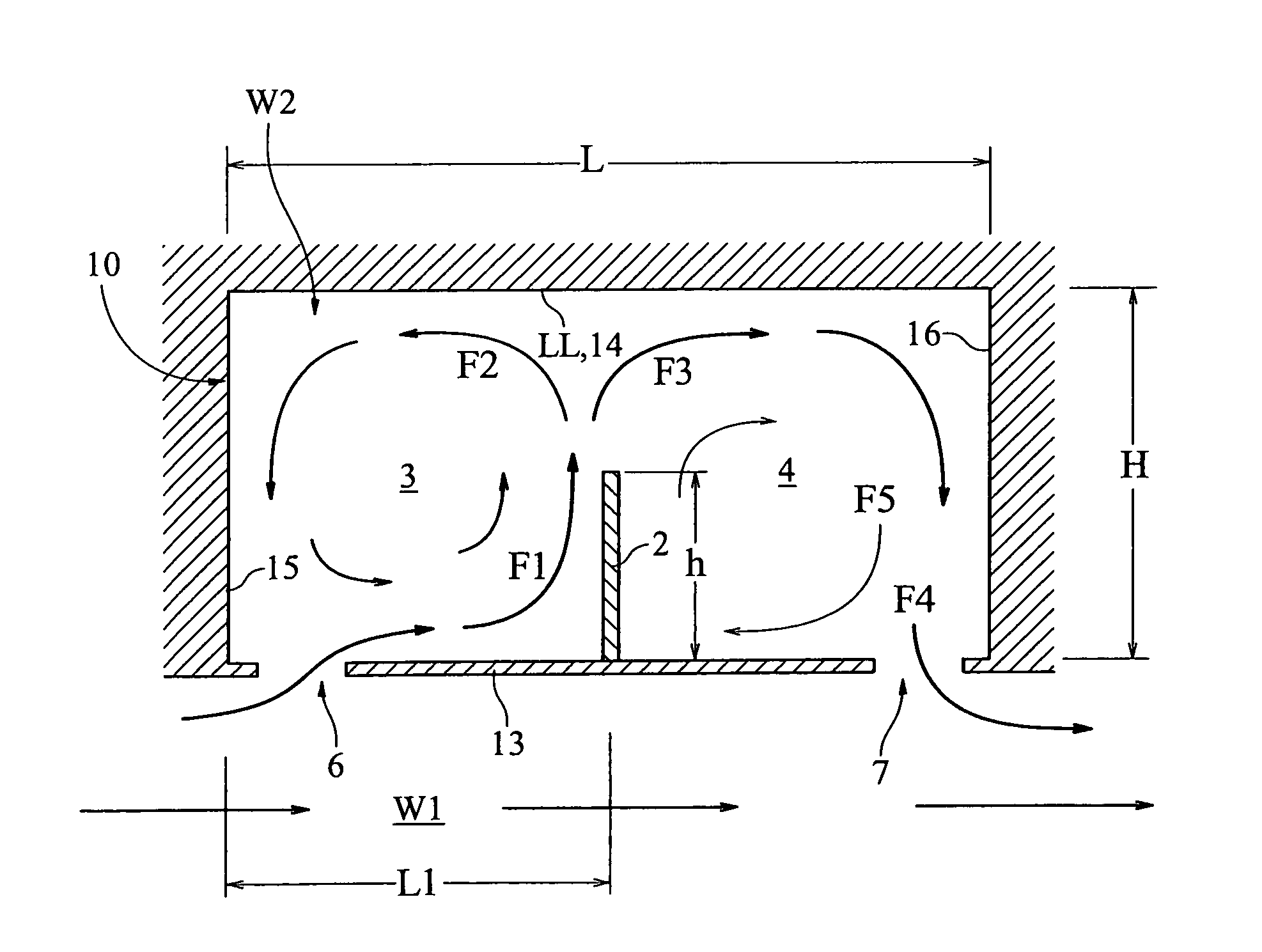
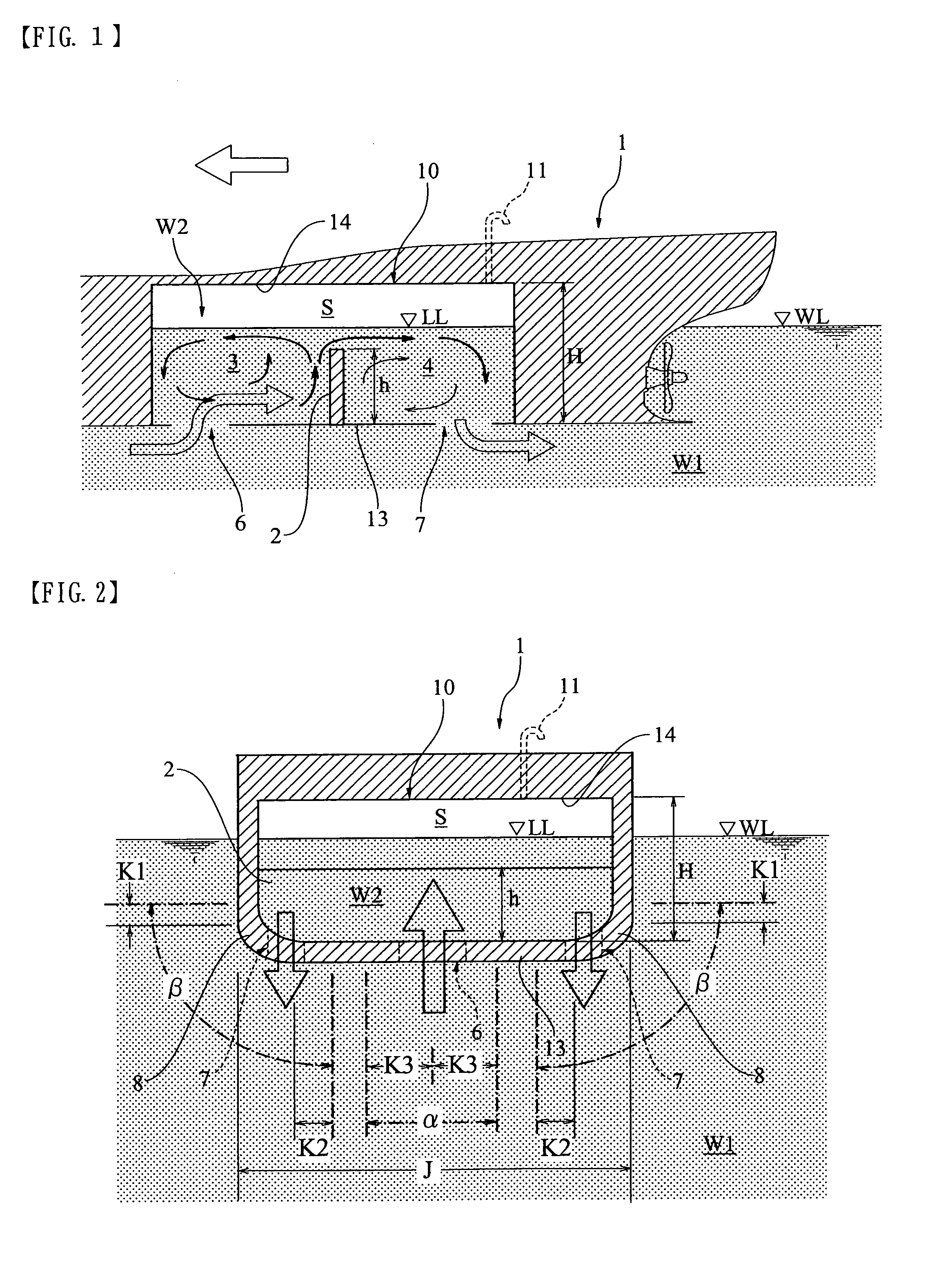
[0078]Preferred examples of the invention will be described below in detail with reference to the accompanying drawings. FIG. 1 is a partial longitudinal cross-sectional view illustrating an example of a ship with a ballast water exchanger according to the present invention. FIG. 2 is a lateral cross-sectional view of the ship shown in FIG. 1.

[0079]A ship 1 is provided with a ballast tank 10 having a partition 2 therein. The height h of the partition 2 is lower than a water surface LL in the tank when the ship is in a lightly loaded or unloaded condition. The partition 2 extends in the widthwise direction of the hull (in the starboard-port direction). The upper end of the partition 2 is spaced apart from a top wall surface 14 by a predetermined distance. The height h is preferably set to be equal to or greater than H×0.2, where H represents the overall height of the ballast tank 10.

[0080]Since the water pressure in the tank is in balance with the water pressure outside the ship, the...


PUM


Abstract

A tank (10) of a ship (1) is provided with an inflow port (6) and an outflow port (7) opening through a bottom of the ship (13). The inflow and outflow ports are spaced apart from each other in a headway direction of the hull. The ports are equipped with closure means (9), which closes the ports so as to ensure hull buoyancy by means of air in the tank. The ports allow seawater outside the ship to flow into the tank through the inflow port and the seawater in the tank to flow out of the ship through the outflow port, with use of headway motion of the ship. A partition (2) provides a weir extending in a widthwise direction of the hull in the tank, and divides a region in the tank into an inflow area (3) and an outflow area (4). The tank, partition, inflow port, outflow port and closure means constitute a ship buoyancy control system.

Description

CROSS REFERENCE TO RELATED APPLICATIONS[0001]This application claims the benefit under 35 U.S.C. Section 371, of PCT International Application No. PCT / JP2007 / 073761, filed Dec. 10, 2007, which claimed priority to Japanese Application No. 2006-332691, filed Dec. 9, 2006 in the Japanese Patent Office, the disclosures of which are hereby incorporated by reference.TECHNICAL FIELD[0002]The present invention relates to a ship buoyancy control system, and particularly to a ballast-free ship buoyancy control system which can be applied to a ballast water exchanger or a ballast water exchange method for exchanging ballast water for seawater outside the ship, or which can be applied to a hull structure of a ballast-free ship.BACKGROUND ART[0003]In general, when a ship is navigated in an unloaded or lightly loaded condition, the ship is charged with ballast water to ensure a predetermined draft so as to not only stabilize the hull but also prevent hull bottom slamming, propeller racing, and ot...

Claims


Application Information

Patent Timeline
Patent Type & Authority Applications(United States)
IPC IPC(8): B63B11/04B63B13/02
CPCB63B11/04B63B13/00B63B2057/005B63B57/02B63B43/06
Inventor ARAI, MAKOTOSUZUKI, KAZUOKORA, KOKI
Owner NAT UNIV CORP YOKOHAMA NAT UNIV
Why Eureka
Try Eureka