Power Converter Circuitry

a power converter and circuit technology, applied in the direction of power conversion systems, dc-dc conversion, electrical apparatus, etc., can solve the problems of loss in chopper operation, achieve high output voltage, reduce wiring costs, and improve redundancy in the event of failure

Active Publication Date: 2010-01-28
SMA SOLAR TECH AG
View PDF3 Cites 124 Cited by
  • Summary
  • Abstract
  • Description
  • Claims
  • Application Information

AI Technical Summary

Benefits of technology

[0007]Another advantage is that the plant may contain a sinusoidal filter and a mean voltage transformer that is not loaded with high di / dt values when switching the power converter.
[0008]The arrangement described has another advantage which is that, in the event of a failure in an inverter or power converter, the defective inverter can be bridged quickly using a bridging switch and that a series-connected diode in the current path can be eliminated. On boost converters, this diode prevents reverse current fed by the transformer coil from flowing into the bridging switch. Prior to switching the by-pass, the AC contactor must be opened in order to prevent the reverse current.
[0009]This circuitry is very suited for solar and photovoltaic plants. In idle operation, e.g., in the morning after sunrise, the solar generator has a high output voltage. The idle voltage usually is more than 20% higher than in the working point during feeding, i.e., it is 20% higher than a maximum power point (MPP) voltage. Thanks to the invention, the higher generator voltage in idle operation does not cause damage to the electronics during starting. The circuitry makes it possible that the solar voltage can be higher than the permissible overall voltage of the power converter circuitry.
[0010]On large solar plants, the series connection allows reducing the wiring expense on the DC side and the costs as a result thereof.
[0011]The invention relies on the observation that the redundancy in the event of a failure can be improved with the bridging switches.
[0012]In the event of a power converter failure, the corresponding power converter is moreover bridged with fewer losses.

Problems solved by technology

During chopper operation, part of the power in the chopper is converted into heat energy so that losses occur in chopper operation.

Method used


Image

  • Power Converter Circuitry
  • Power Converter Circuitry
  • Power Converter Circuitry

Examples


Embodiment Construction

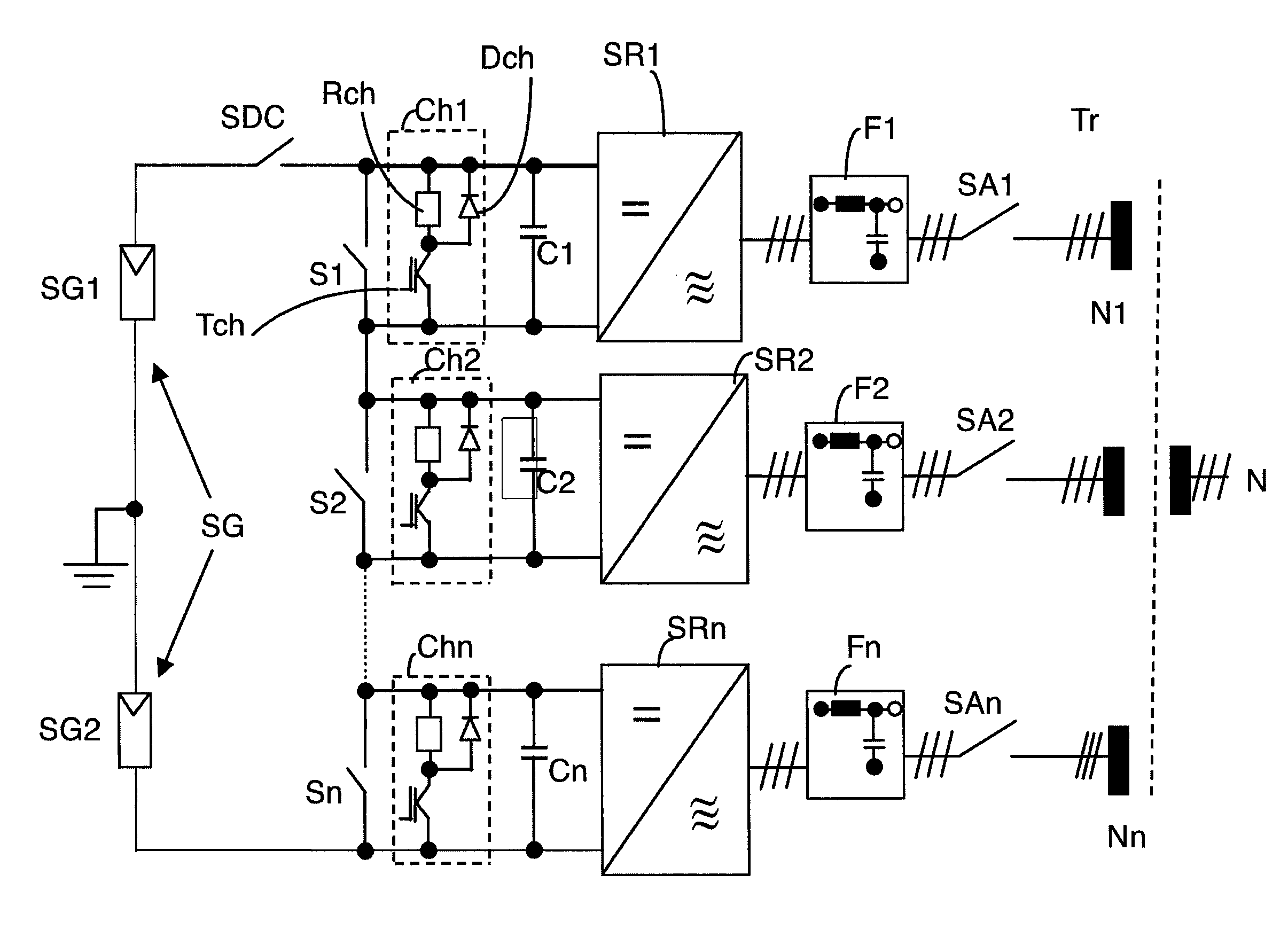
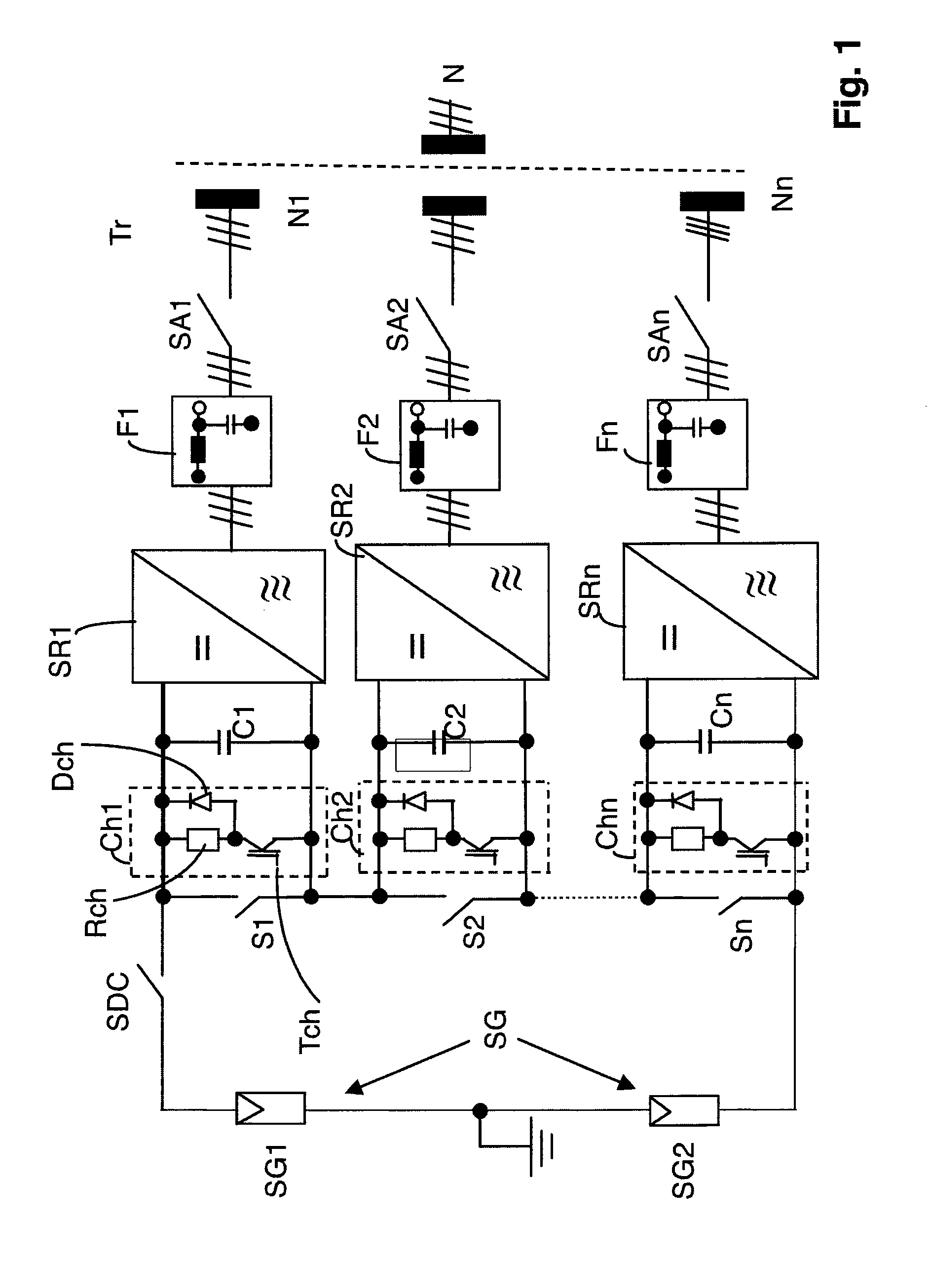
[0026]FIG. 1 shows a preferred embodiment of a power converter circuitry of the invention for a solar plant for feeding into a grid N. It incorporates several power converters SR1 through SRn which are series-connected downstream of a solar or photovoltaic generator SG. By series-connecting several power converters SR1 through SRn the wiring expense is reduced on the DC side.

[0027]The generator SG consists of two series-connected photovoltaic groups SG1, SG2, which are grounded at their connection point so that a positive, a negative and a zero volt voltage, meaning a bipolar voltage or center point grounding is provided. Each photovoltaic group SG1, SG2 may consist of several parallel and / or series-connected solar cells or modules in order to deliver the required voltage or power. Alternatively, there may be provided one single module group with grounding at the positive pole, the negative pole or without grounding.

[0028]Several DC contactors S1 through Sn are also connected in ser...


PUM


Abstract

A power converter circuitry for converting a DC voltage generated by a generator with varying output power in the mean voltage range into an alternating voltage for feeding into a grid, with several series-connected power converters, which are connected in parallel with said generator, as well as with a controllable bridging switch for each power converter, said bridging switch lying in a direct voltage intermediate circuit and bridging the respective power converter in the closed condition, is intended to be used for a photovoltaic generator. This is achieved in that a resistance chopper is connected between each power converter and the generator, no input diode being provided in the current path from the generator to the power converter, and that each bridging switch is connected in parallel with the resistance chopper in the direct voltage intermediate circuit.

Description

BACKGROUND OF THE INVENTION[0001]A power converter circuitry for converting a direct voltage of 1500 V into an alternating voltage is known from railway technology and from US 2005 / 284673 A1. For this purpose, several series-connected power converters are utilized, each power converter having a controllable bridging switch. Each bridging switch lies in a direct voltage intermediate circuit which bridges the respective one of the power converters when closed.[0002]In wind power plants as they are described in EP 1 921 738 A2, a resistance chopper is connected in parallel with a full-bridge circuit of an inverter and with a capacitor in the direct voltage intermediate circuit. The direct voltage can be adapted by adding the chopper to the circuit.[0003]The publication Calais M. et al, “Multilevel converters for single-phase grid connected photovoltaic systems: an overview”, Solar Energy, Pergamon Press. Oxford, GB, Bd. 66, Nr. 5, 1. August 1999, pages 325-335, xp 004362671, issn 0038-...

Claims


Application Information

Patent Timeline
Patent Type & Authority Applications(United States)
IPC IPC(8): H02M7/44H02H7/122
CPCH02J3/38H02M2001/322H02M2001/0074H02M7/44H02M1/0074H02M1/322H02M3/24
Inventor FALK, ANDREAS
Owner SMA SOLAR TECH AG
Why Eureka
Try Eureka