High efficiency and high throughput cascade scrub wash machine for rigid magnetic recording media

a rigid magnetic recording media, high efficiency technology, applied in mechanical recording, cleaning equipment, instruments, etc., can solve the problems of increasing the risk that one of the sliding surfaces may be damaged during operation, damage and need to be removed from the sliding surfaces, and the surface cannot be too smooth, so as to eliminate the the effect of eliminating the rotation slippage of the disk

Active Publication Date: 2010-01-28
SEAGATE TECH LLC
View PDF5 Cites 1 Cited by
  • Summary
  • Abstract
  • Description
  • Claims
  • Application Information

AI Technical Summary

Benefits of technology

[0014]This invention relates to a disk cleaning scrub module comprising a scrub lane and a plurality of brushes that rotates and scrub washes a plurality of disks having a diameter D in the scrub lane, wherein a disk-to-disk center distance for scrub wash of the plurality of the disks is S and a ratio of S / D is greater than 1 and less than 1.6. Preferably, at least a portion of the brushes have a core that is a step core having two diameter sizes along the length of the core such that a larger diameter section of the brush pushes down with greater force on the disk than a smaller diameter section of the brush during scrub wash of the disk by the brush, thereby rotating the disk. The disk cleaning scrub module further comprises a drive belt having a groove to allow for a snug fit with the other diameter (OD) of the plurality of disks. Preferably, a linear velocity of the drive belt and a rotation speed of the brush having a step core are such that rotation slippage of the disk on the drive belt is substantially eliminated. Preferably, the linear velocity of the drive belt and the rotation speed of the brush are adjusted by software control to substantially eliminate slippage of the disk on the drive belt. The disk cleaning scrub module further comprises a transfer chain having advance fingers positioned such that the ratio of S / D is greater than 1 and less than 1.5. Preferably, at least a portion of the advance fingers comprise at least two rollers. Preferably, a single scrub lane scrub washes at least 5 disks simultaneously. Preferably, the brushes are mounted on a mandrel. Preferably, the mandrel comprises a hollow cross-section in the center of the mandrel to allow a fluid to flow through the mandrel and exit through openings on a surface the mandrel.
[0015]Another embodiment relates to a method of cleaning a plurality of disks in a disk cleaning scrub module comprising a scrub lane and a plurality of brushes that rotates and scrub washes a plurality of disks having a diameter D in the scrub lane, wherein a disk-to-disk center distance for scrub wash of the plurality of the disks is S, the method comprises positioning the disk in the scrub lane such that a ratio of S / D is greater than 1 and less than 1.6 and rotating the brushes.

Problems solved by technology

If there are particles of a large enough dimension between the sliding surfaces, then there is an increased risk that one of the sliding surfaces may be damaged during operation.
Particles can cause damage and need to be removed from the sliding surfaces before assembly of the disc drive 100.
So, the surface cannot be too smooth, or the drive lead will end up sticking to the disk, and it cannot be too rough either, or the head will end up getting caught in the microscopic bumps on the surface.
Some larger contaminants in the range of 1-5 microns are easier to remove, but smaller contaminants in the range of 0.1 micron to 1.0 micron are much more difficult to remove.
Contaminants on the surface of the disk can degrade the performance of the rigid magnetic medium.
Contaminants that protrude above the flying height of the read / write heads can cause these heads to crash—just like an airplane hitting a small hill.
Contaminants that are below the flying height of the read / write heads, but are large enough, will cause a loss of magnetic signal.
All these forms of contamination directly lead to magnetic performance failure at the drive.
This is a very huge challenge because of the very small sizes of the sub-micron particles and contaminants.
In particular, the requirement to further reduce the flying height of the head imposed by increasingly higher recording density and capacity renders the disk drive particularly vulnerable to head crash due to accidental glide hits of the head and media.
The direct result of these demands is tending towards low yield due to less defect tolerance at the surface of the media.

Method used


Image

  • High efficiency and high throughput cascade  scrub wash machine for rigid magnetic recording media
  • High efficiency and high throughput cascade  scrub wash machine for rigid magnetic recording media
  • High efficiency and high throughput cascade  scrub wash machine for rigid magnetic recording media

Examples


examples

[0061]In the current cascade scrub module of the Oliver 2000 machine, the transfer chain was re-designed to allow for reduced ratio of disk-to-disk gap to disk diameter. FIG. 3 shows a 95-mm diameter disk transfer chain in which the advance fingers were two V-rollers each. This design reduced the disk-to-disk gap between the disks. For 65-mm disk, the each of the advance fingers had a singe V-roller. FIG. 4 shows a sketch of the disks and mandrel configuration of an embodiment of this invention. The embodiment of the invention shown in FIGS. 3 and 4 have a new chain design, a new mandrel design, and a software to control the movement of the disk through the scrub wash machine.

[0062]Another feature of the invention is a new brush having a step core. This brush has been designed to allow for reduced disk-to-disk gap between disks; and allows for more positive frictional forces to help rotate the disk as demonstrated by the schematics in FIG. 5, wherein the top schematic shows a straig...


PUM

PropertyMeasurementUnit
flying heightaaaaaaaaaa
lengthaaaaaaaaaa
diameteraaaaaaaaaa

Abstract

A disk cleaning scrub module comprising a scrub lane and a plurality of brushes that rotates and scrub washes a plurality of disks having a diameter D in the scrub lane, wherein a disk-to-disk center distance for scrub wash of the plurality of the disks is S and a ratio of S/D is greater than 1 and less than 1.6 is disclosed.

Description

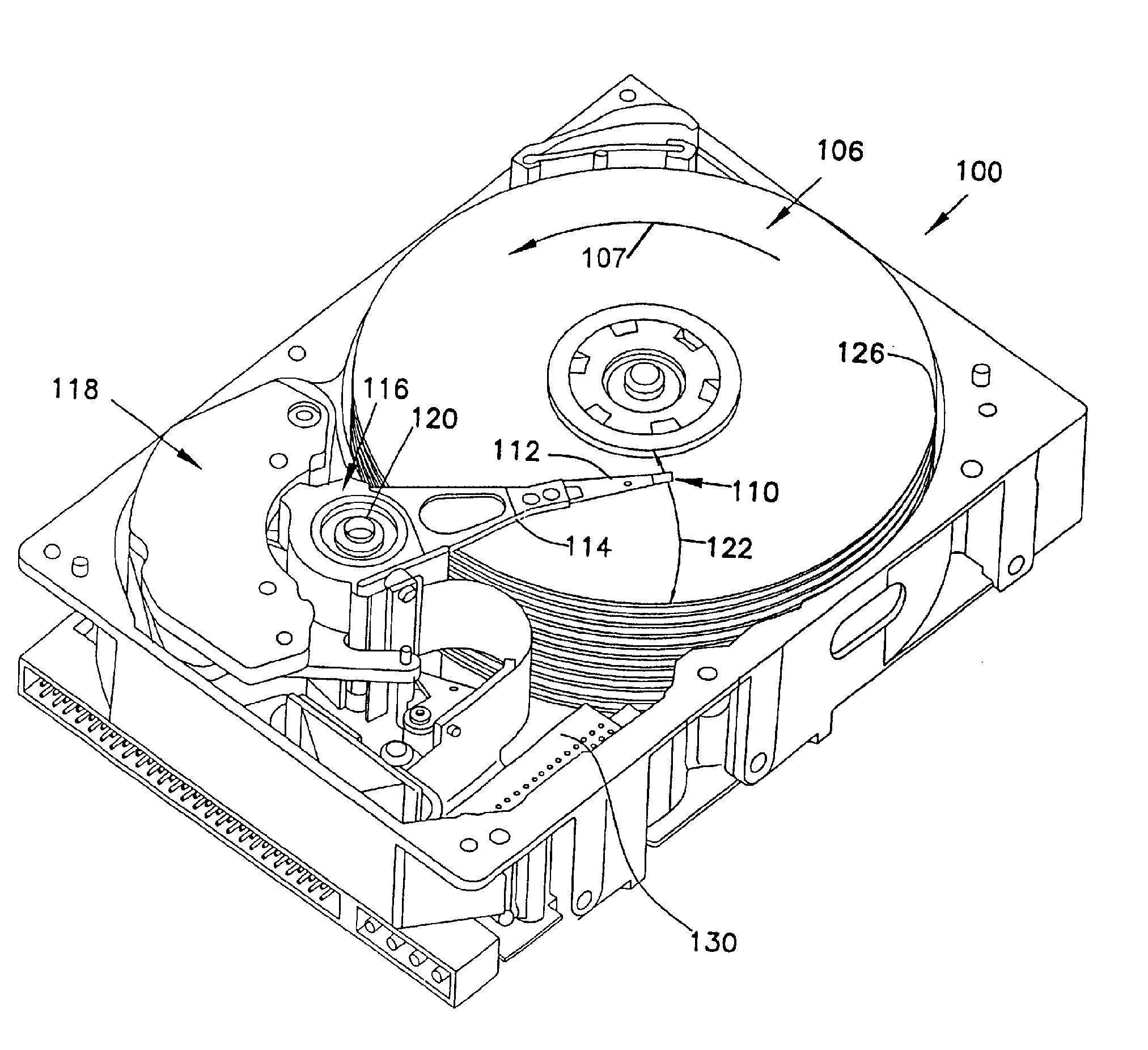
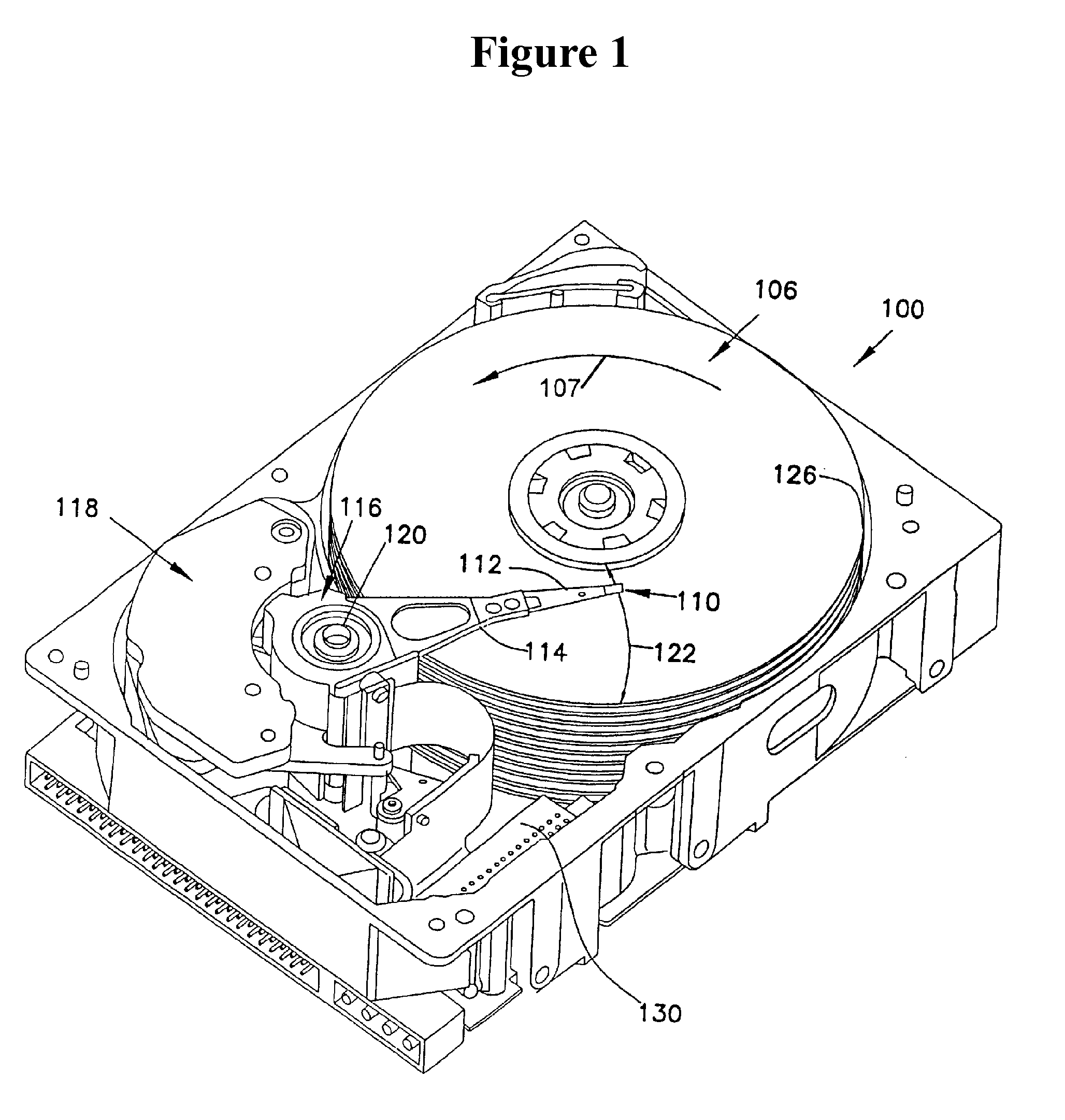
BACKGROUND[0001]Magnetic disks and disk drives are conventionally employed for storing data in magnetizable form. Preferably, one or more disks are rotated on a central axis in combination with data transducing heads positioned in close proximity to the recording surfaces of the disks and moved generally radially with respect thereto. Magnetic disks are usually housed in a magnetic disk unit in a stationary state with a magnetic head having a specific load elastically in contact with and pressed against the surface of the disk. Data are written onto and read from a rapidly rotating recording disk by means of a magnetic head transducer assembly that flies closely over the surface of the disk. Preferably, each face of each disk will have its own independent head.[0002]In FIG. 1, an embodiment of a disc drive storage device 100 is illustrated. Disc drive 100 includes a disc pack 126 having storage surfaces 106 that are typically layers of magnetic material that are deposited using micr...

Claims


Application Information

Patent Timeline
Patent Type & Authority Applications(United States)
IPC IPC(8): G11B23/50
CPCG11B23/505
Inventor LIU, YOUMINLIGUTOM, RITOPOMPLIANO, KENNITHBUI, YOUNGHOU, JENNIFERTUMAN, JAMES
Owner SEAGATE TECH LLC
Why Eureka
Try Eureka