Device and method for x-ray tube focal spot size and position control

a technology of x-ray tubes and focal spots, applied in the direction of electrical discharge tubes, basic electric elements, electrical apparatus, etc., can solve the problems of mechanical and electrical properties, inability to compensate for changes in focal spot size, difficulty in maintaining required tolerances, etc., and achieve the effect of improving the control of focal spot parameters

Inactive Publication Date: 2010-01-28
KONINKLIJKE PHILIPS ELECTRONICS NV
View PDF9 Cites 57 Cited by
  • Summary
  • Abstract
  • Description
  • Claims
  • Application Information

AI Technical Summary

Benefits of technology

[0005]It would be desirable to provide a method and devi...

Problems solved by technology

Maintaining the required tolerances is difficult to realise because during a CT scan many parts of an X-ray tube heat up considerably, leading to changes of mechanical and electrical properties, which influence for example the focal spot size and position.
There is, however, no compensation for changes in the focal spot size, so th...

Method used


Image

  • Device and method for x-ray tube focal spot size and position control
  • Device and method for x-ray tube focal spot size and position control
  • Device and method for x-ray tube focal spot size and position control

Examples


Embodiment Construction

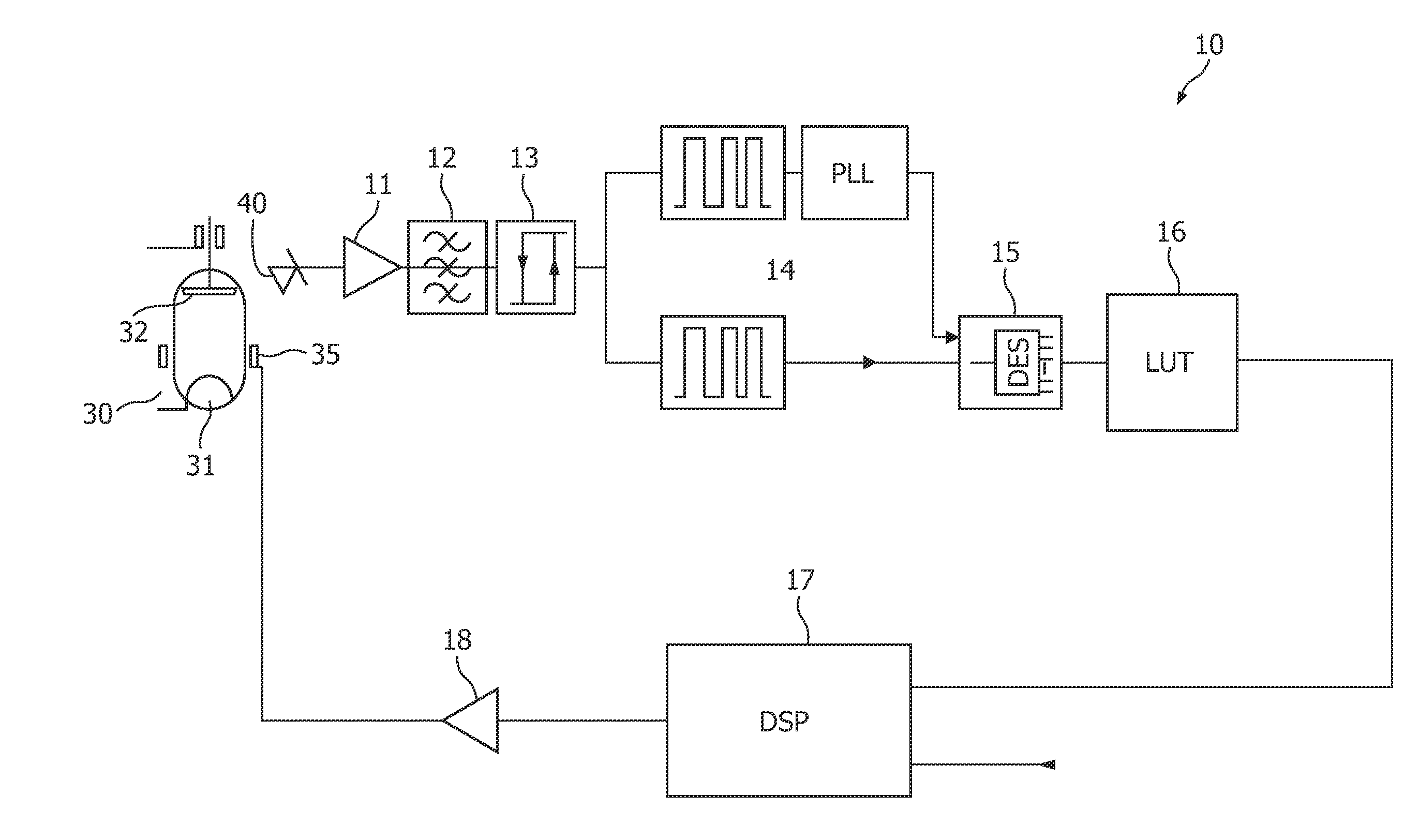
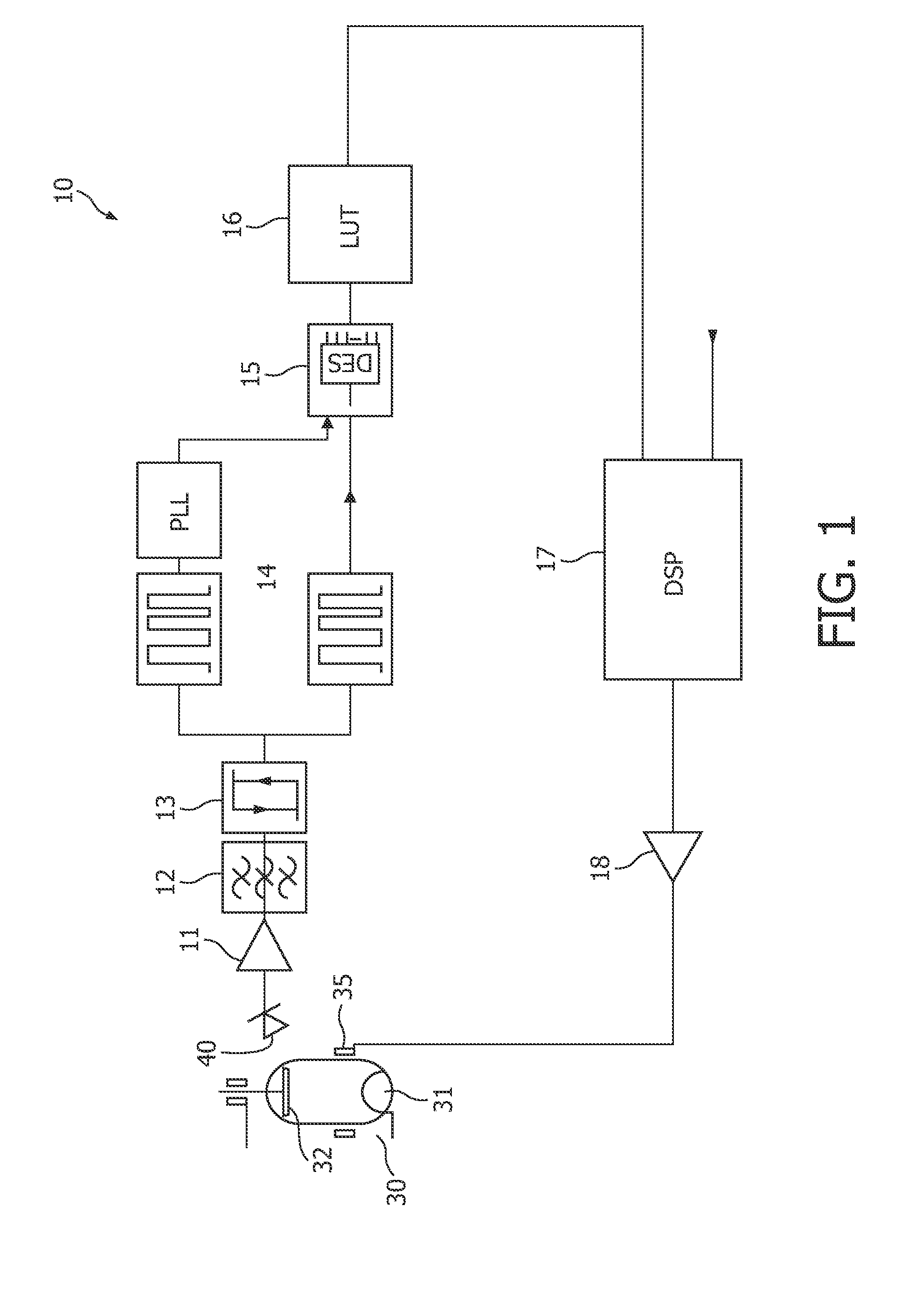
[0041]FIG. 1 shows a device for providing a controlling signal for controlling focal spot parameters of a focal spot on an X-ray tube anode 32. The device comprises an interface 11 serving for receiving a signal having a characteristic pattern depending on stray electrons detected in the X-ray tube 30. The X-ray tube is illustrated only for explanation purposes, and therefore schematically. The X-ray tube comprises an emitter 31 and an anode 32, wherein the emitter is adapted to emit electrons towards the anode. The detection unit 40 is illustrated outside the X-ray tube 30 for explanation purposes only, and can also be placed within the X-ray tube 30, in particular when detecting stray electrons. The X-ray tube also comprises deflection coils 35. The interface 11 may be a terminal, however, can also be provided with an amplifier for the amplification of the received signal. The interface 11 may also include any processing utilities for processing of the received signal, where it is...


PUM


Abstract

A device and method for X-ray tube focal spot parameter control, wherein stray electrons are detected in an X-ray tube. The detected electrons lead to a signal having a characteristic pattern. The characteristic pattern may be evaluated, and based on the evaluation a controlling signal may be outputted so that a fast and exact controlling of the operating parameters of an X-ray tube may be carried out based on the detected stray electrons.

Description

[0001]The present invention relates to a device and method for X-ray tube focal spot parameter control, and in particular to a focal spot size and position control based on the detection of strayed electrons, such that the state and condition of the focal spot can be determined and a fast controlling thereof can be carried out to improve the efficiency of an x-ray tube operation.BACKGROUND OF THE INVENTION[0002]In an X-ray tube, about 40% of the electrons hitting the anode are reflected (strayed). The amount of these stray electrons hitting any given region inside the X-ray tube can vary considerably. The reason may be, for example, a deviation of focal spot parameters from the optimum focal spot parameters, wherein the focal spot parameters may be the focal spot size or the focal spot position. In many applications of x-ray examination apparatuses, only very small tolerances for variations of focal spot parameters, e.g. focal spot size and focal spot positions, can be tolerated dur...

Claims


Application Information

Patent Timeline
IPC IPC(8): H01J35/14
CPCH05G1/52H01J35/14H01J35/147H01J35/153
Inventor KOCH, LOTHARCHROST, WOLFGANGROLOFF, HORST
Owner KONINKLIJKE PHILIPS ELECTRONICS NV
Why Eureka
Try Eureka