Method for fabricating three dimensional models

a three-dimensional model and model technology, applied in the direction of additive manufacturing processes, manufacturing tools, coatings, etc., can solve the problems of complex designs, complex designs, and inability to meet the needs of such purposes, and most conventional fabrication methods are unsuitable for such purposes, and can not meet the needs of complex designs and computer numerical control machine processes. significant limitations as regards the types or configurations of parts that can be fabricated

Inactive Publication Date: 2010-01-28
SOLIDSCAPE
View PDF11 Cites 51 Cited by
  • Summary
  • Abstract
  • Description
  • Claims
  • Application Information

AI Technical Summary

Benefits of technology

[0041]In yet another embodiment, the step of removing the three dimensional model from the composite model may include a common removal process for simultaneous removal of the second and the third materials that does not effect the first material, and the external surface(s) of the final three dimensional model are formed of the first material.
[0042]In a still further embodiment, the step of removing the three dimensional model from the composite model may include a common removal process for simultaneous removal of the second and the third materials, that does not effect the first material, followed by a separate removal process for removal of the first material that does not effect the second material, and the external surface(s) of the final three dimensional model are formed of the second material.

Problems solved by technology

Most conventional fabrication methods, however, are unsuitable for such purposes.
Manual machining, for example, is sometimes suitable for relatively simple designs but is too slow and expensive for complex designs and Computer Numerically Controlled (CNC) machine processes, while suitable for complex designs, have significant limitations as regards the types or configurations of parts that can be fabricated.
It will therefore be apparent that the 3D modeling systems of the prior art suffer from a number of inherent disadvantages.
For example, the deposition of the model and sacrificial material on a drop-by-drop basis is very time consuming, particularly when a significant proportion of the material is subsequently sacrificed, or wasted, in order to obtain the final part to be manufactured.
In a typical part, however, much of the deposited material is thereby merely sacrificial material that must be subsequently removed, so that much of the deposited material, as well as the time required to deposit the material, is effectively wasted with respect to the final part.
The user of multiple drop-on demand print heads, however, significantly increases the complexity and cost of the system.
In addition, drop-on-demand print heads typically have relatively small jetting orifices, which limit the rate at which material can be deposited, limit the types of material that can be deposited to those materials capable of being ejected as drops through a small orifice, and reduce print head reliability because the small orifices are more readily subject to blockage.
In addition, it has often been difficult, in systems or the prior art, to achieve the desired dimensional tolerances, surface textures and finished part quality.
The method still, however, requires the time consuming drop-by-drop deposition of significant amounts of mold material, particularly in forming the sacrificial “cubes” for temporary support of overhanging, cantilevered and / or undercut regions and temporary filling of voids, as well as possible difficulties in subsequently removing the “cubes”.

Method used


Image

  • Method for fabricating three dimensional models
  • Method for fabricating three dimensional models
  • Method for fabricating three dimensional models

Examples


Embodiment Construction

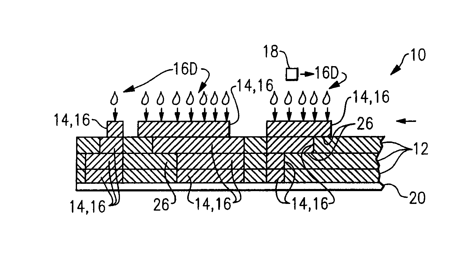
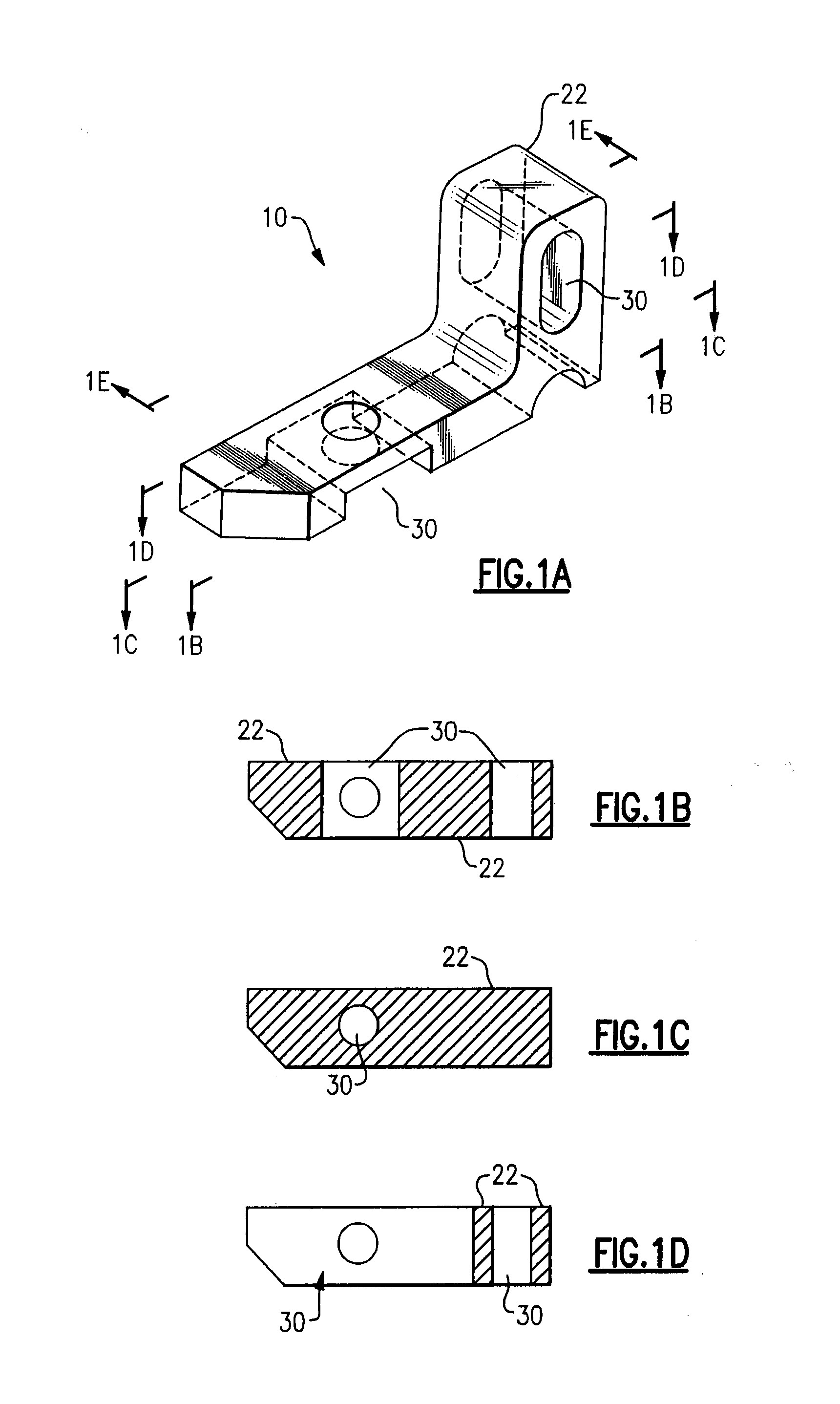
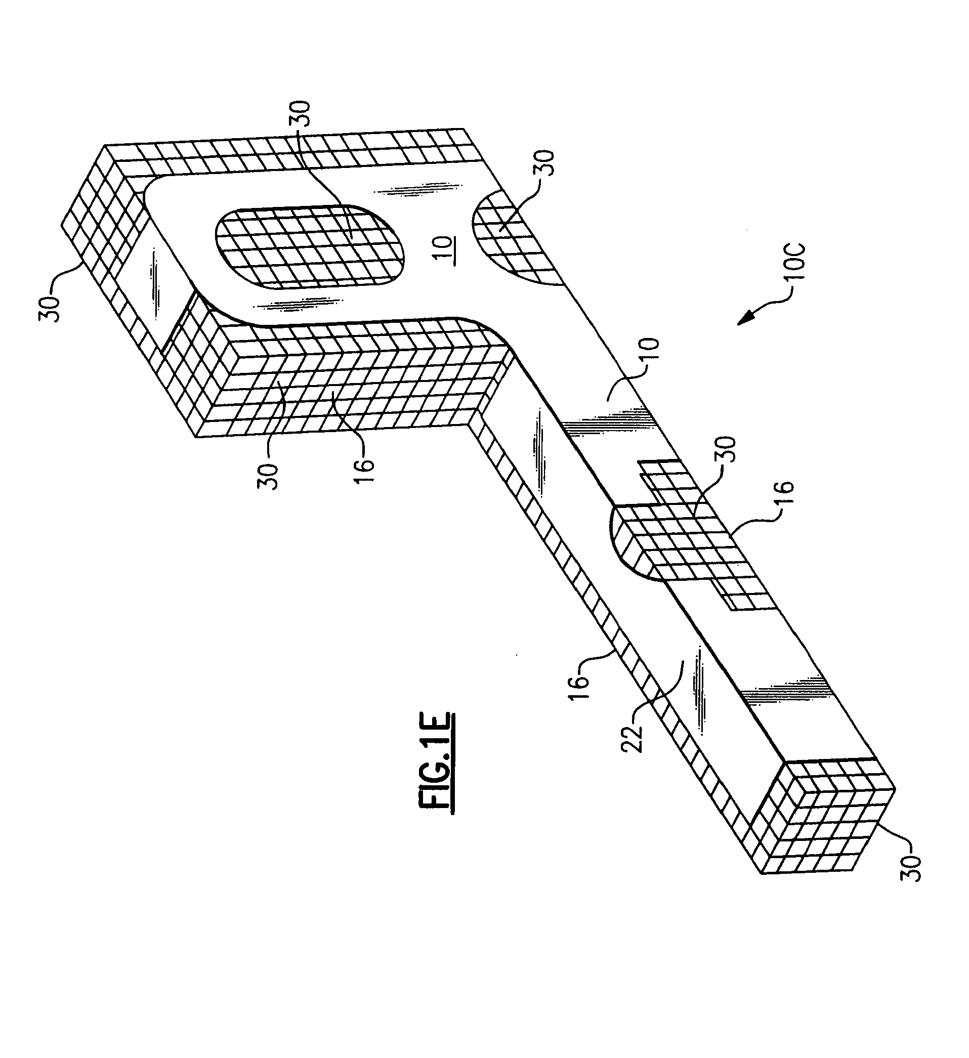
[0053]The method and apparatus of the present invention for fabricating three dimensional models is a further development and improvement of the method and apparatus for fabricating three dimensional models described U.S. Patent Publication No. 2007 / 0029693 A1 and provides a significant improvement with respect to the time required for fabrication of such parts or structures. As such, and in order to provide a context and description of the base technology of the present invention, the following will begin with a summarized description of the method and apparatus for fabrication of three dimensional models as described in U.S. Patent Publication No. 2007 / 0029693 A1, the contents of which are incorporated herein by reference.

[0054]A. Fabrication of Three Dimensional Models as Described in U.S. Patent Publication No. 2007 / 0029693 A1.

[0055]Therefore, first considering the basic method and apparatus for fabricating three dimensional models as described in U.S. Patent Publication No. 200...


PUM

PropertyMeasurementUnit
widthaaaaaaaaaa
widthaaaaaaaaaa
temperatureaaaaaaaaaa

Abstract

A method for fabricating a three dimensional model by fabricating a composite model formed of a plurality of successive layers comprised of one or more materials wherein each successive layer is formed by depositing at least first material delineating boundaries of at least one first area of the layer by a drop-by-drop deposition and depositing at least a second material over the layer by a rapid deposition method, and may include the deposition of a third material by a drop-by-drop or rapid deposition method and will include planing the layer to a uniform thickness and selectively removing the first and second materials, and third material if present, by successive removal methods, each of which effects only one of the materials.

Description

CROSS REFERENCES TO RELATED APPLICATIONS[0001]The present Patent Application is related to and claims benefit of Provisional Patent Application Ser. No. 61 / 137,189 filed Jul. 28, 2008 by John Theodore WIGAND, Calvin McCoy WINEY III and Michael VARANKA for a METHOD AND APPARATUS FOR FABRICATING THREE DIMENSIONAL MODELS, and is further related to and claims benefit of U.S. patent application Ser. No. 11 / 445,516 filed Jun. 2, 2006 by John Theodore WIGAND, Calvin McCoyWINEY III and Michael VARANKA for a METHOD AND APPARATUS FOR FABRICATING THREE DIMENSIONAL MODELS, corresponding PCT Patent Application Serial No. PCT / US2006 / 029696 filed Jul. 28, 2006, both of which are assigned to the assignee of the present Patent Application, and corresponding U.S. Patent Publication No. 2007 / 0029693 Al. U.S. patent application Ser. No. 11 / 445,516 is in turn related to and claims benefit of Provisional Patent Application Ser. No. 60 / 705,138 filed Aug. 3, 2005 by John Theodore Wigand, Calvin McCoy Winey...

Claims


Application Information

Patent Timeline
Patent Type & Authority Applications(United States)
IPC IPC(8): B05D3/00
CPCB29C67/0059B29C64/112B33Y10/00B29C64/188
Inventor VARANKA, MICHAELWIGAND, JOHN THEODOREWINEY, CALVIN MCCOY
Owner SOLIDSCAPE
Why Eureka
Try Eureka