Substrate release methods and apparatuses

a technology of substrate and template, applied in the direction of electrical apparatus, basic electric elements, semiconductor devices, etc., can solve the problems of prior art methods that are not suited to fracture porous silicon, many prior art release methods are either less effective or not suitable for fracture porous silicon, so as to reduce the damage to both the substrate and the template, and minimize complexity

Inactive Publication Date: 2010-01-28
BEAMREACH SOLAR INC
View PDF4 Cites 76 Cited by
  • Summary
  • Abstract
  • Description
  • Claims
  • Application Information

AI Technical Summary

Benefits of technology

[0014]The following description is not to be taken in a limiting sense, but is made for the purpose of describing the general principles of the present disclosure. The scope of the present disclosure should be determined with reference to the claims. The methods of the present disclosure substantially reduce disadvantages of prior art methods, and are intended to separate a 3-D TFSS substrate from 3-D silicon templates by fracturing a middle porous silicon layer. Further, the methods of the present disclosure aim to reduce damage to both the TFSS substrate and template while also minimizing complexity.

Problems solved by technology

However, prior methods have several drawbacks.
Prior art methods may not be suited to fracture the porous silicon, while mitigating damage to both the template and 3-D TFSS.
Without the top supporting plate, many of the prior art release methods are either less effective or cause mechanical damage to the released thin-film.
U.S. application Ser. No. 11 / 868,489 discloses a 3-D TFSS which is not conducive to the use of a top supporting plate for release and post-release processes because: (i) it is not convenient to bond a supporting plate on top of the square 3-D TFSS to be released while preventing the supporting plate from attaching to the wafer surface outside of the 3-D TFSS square; (ii) it is difficult to de-bond the supporting plate from the released 3-D TFSS.
Such a release mechanism works well for a planar release, however it does not work for the 3-D TFSS release for the following reasons: (i) because of its three dimensional structural design, the early released portion of honey-comb structure can not be tilted.
A slight out-of-plane curving by an external force or an intrinsic stress will have the 3-D TFSS locked into the template and prevent a full release; (ii) larger external energy / force applied unevenly to the partially released and locked-in 3-D TFSS could cause mechanical damages.
When a porous silicon layer is subjected to compressive, tensile, or shearing forces, it can be fractured, collapsed, or mechanically destroyed.
This method not only succumbs to the difficulties of the prior art method mentioned above, but is also complex and requires precise alignment of the fluid injection nozzle with the porous silicon layer so as not to damage the thin-film layer.
Besides succumbing to the disadvantages mentioned previously, these methods may often damage the template layer which is undesirable for releasing TFSS substrate of U.S. application Ser. No. 11 / 868,489.

Method used


Image

  • Substrate release methods and apparatuses
  • Substrate release methods and apparatuses
  • Substrate release methods and apparatuses

Examples


Embodiment Construction

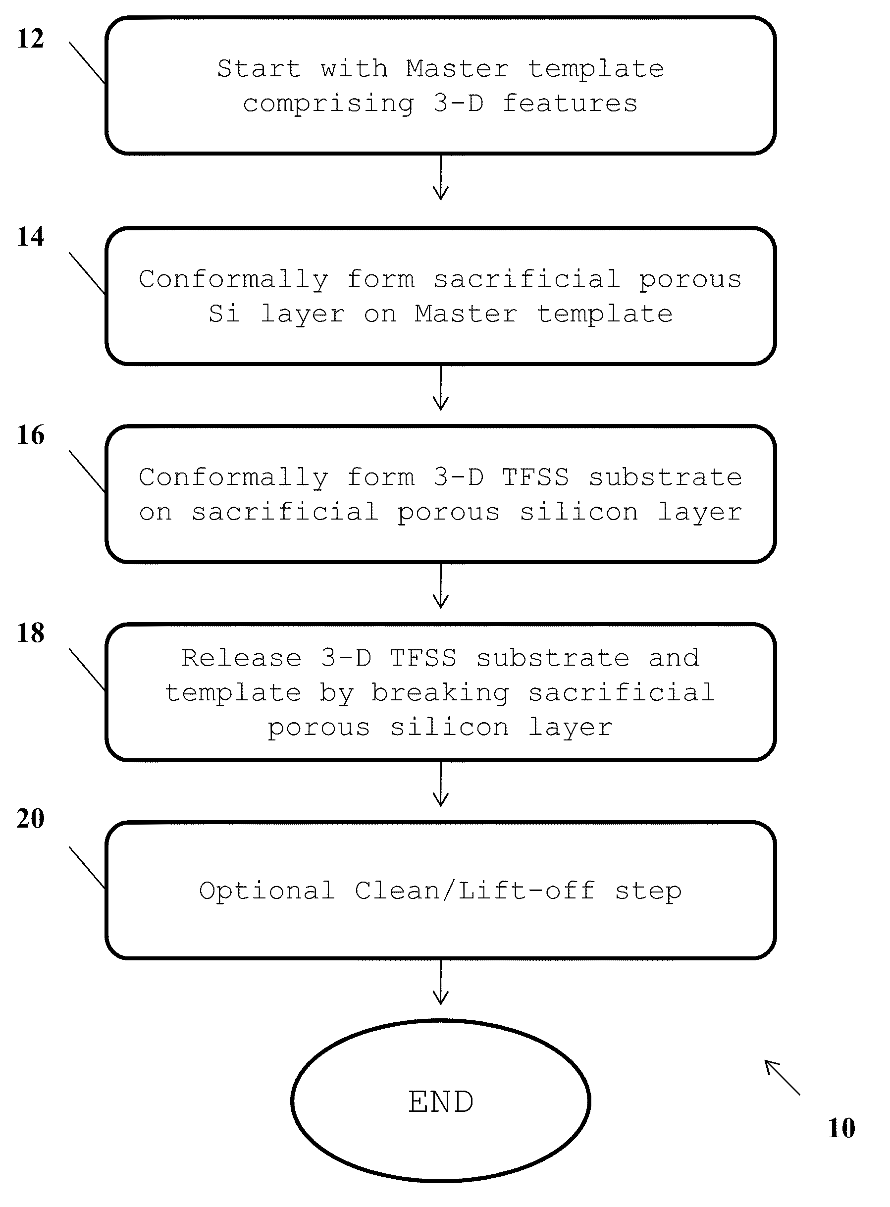
[0051]The following description is not to be taken in a limiting sense, but is made for the purpose of describing the general principles of the present disclosure. The scope of the present disclosure should be determined with reference to the claims. And although described with reference to the manufacture and separation of three-dimensional thin-film semiconductor substrate (3-D TFSS), a person skilled in the art could apply the principles discussed herein to the manufacturing of any multi-dimensional substrate.

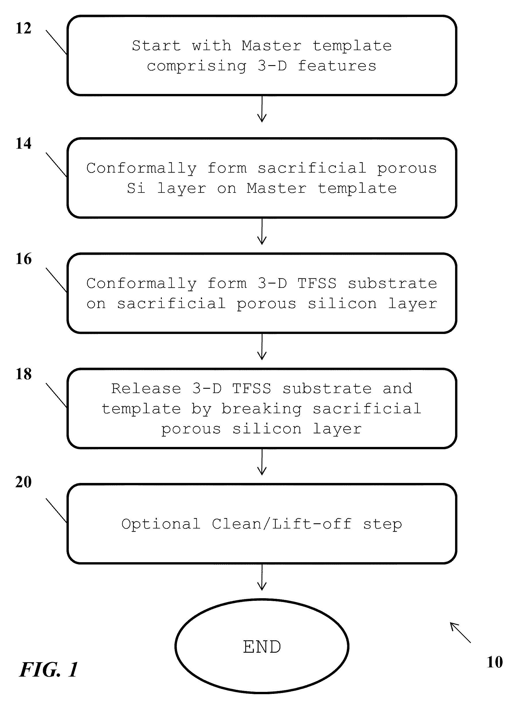
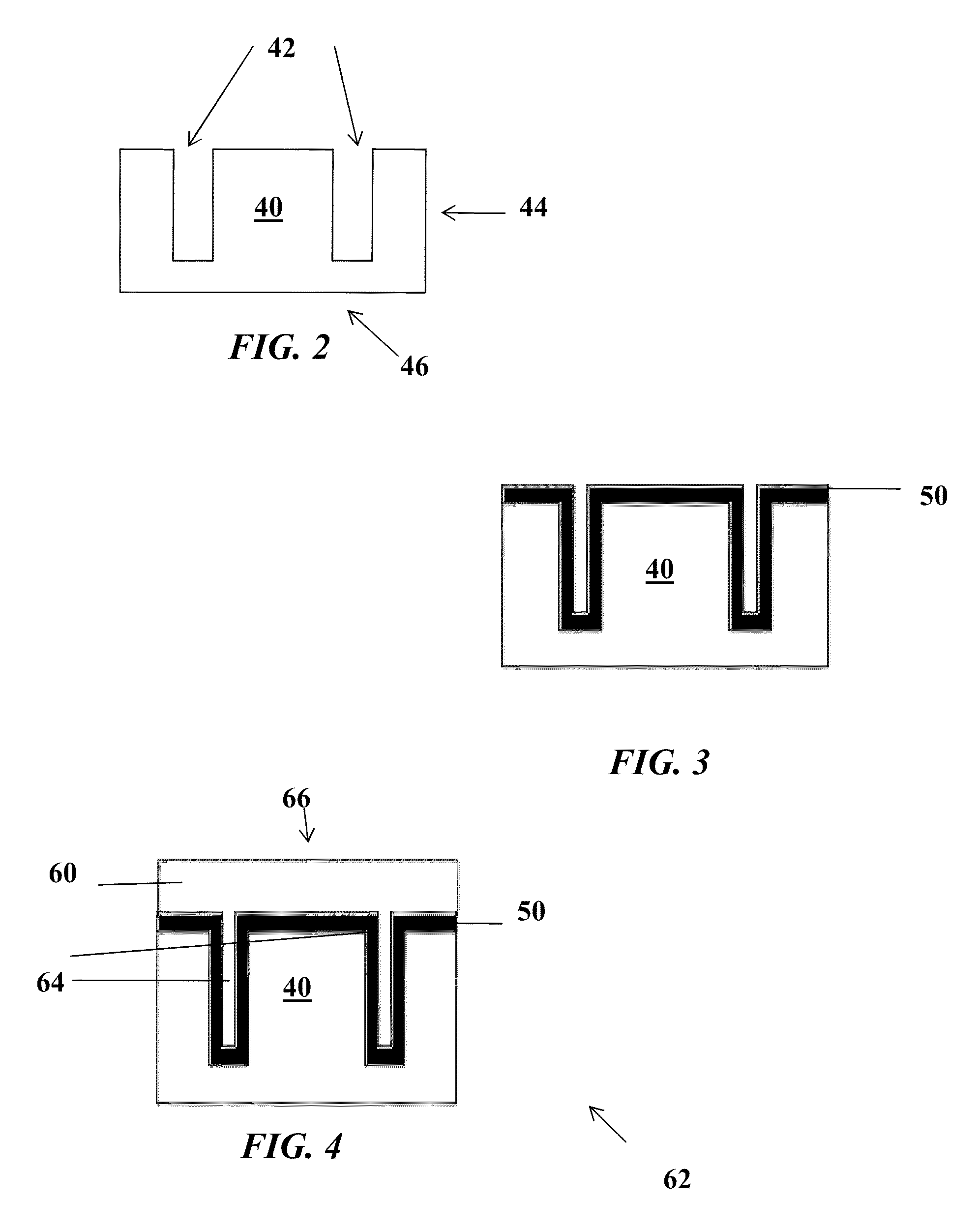
[0052]Preferred embodiments of the present disclosure are illustrated in the drawings, like numbers being used to refer to like and corresponding parts of the various drawings. The innovative 3-D TFSS substrate designs and technologies of the current disclosure are based on the use of a three-dimensional, self-supporting, semiconductor thin film, deposited on and released from a reusable crystalline (embodiments include, but are not limited to, monocrystalline or multicrysta...


PUM


Abstract

The present disclosure relates to methods and apparatuses for fracturing or breaking a buried porous semiconductor layer to separate a 3-D thin-film semiconductor semiconductor (TFSS) substrate from a 3-D crystalline semiconductor template. The method involves forming a sacrificial porous semiconductor layer on the 3-D features of the template. A variety of techniques may be used to fracture and release the mechanically weak porous semiconductor layer without damaging the TFSS substrate layer or the template layer such as pressure variations, thermal stress generation, and mechanical bending. The methods also allow for processing three dimensional features not possible with current separation processes. Optional cleaning and final lift-off steps may be performed as part of the release step or after the release step.

Description

CROSS-REFERENCE TO RELATED APPLICATIONS[0001]The present U.S. Utility patent application claims priority pursuant to 35 U.S.C. §119(e) to the following U.S. Provisional Patent Application which is hereby incorporated herein by reference in its entirety and made part of the present U.S. Utility patent application for all purposes:[0002]a. U.S. Provisional Application Ser. No. 61 / 056,722, entitled “SUBSTRATE RELEASE METHODS AND APPARATUSES,” (Attorney Docket No. SOLT009USP), filed on May 28, 2008, pending.[0003]The present U.S. Utility patent application is related to and incorporates by reference the following copending U.S. patent application in its entirety and is made part of the present U.S. Utility patent application for all purposes:[0004]1. U.S. Utility application Ser. No. 11 / 868,489, entitled “METHOD FOR MANUFACTURING THREE-DIMENSIONAL THIN FILM SOLAR CELLS,” (Attorney Docket No. SOLT002US0), filed Oct. 6, 2007, pendingFIELD OF THE INVENTION[0005]This disclosure relates in g...

Claims


Application Information

Patent Timeline
Patent Type & Authority Applications(United States)
IPC IPC(8): H01L21/762H01L21/20
CPCH01L31/18H01L21/76259
Inventor WANG, DAVID XUAN-QIMOSLEHI, MEHRDAD M.
Owner BEAMREACH SOLAR INC
Why Eureka
Try Eureka