
Pilot signal transmission in a radio communication system

a radio communication system and pilot signal technology, applied in power management, sustainable buildings, high-level techniques, etc., can solve the problems of reducing the capacity of the system, generating a substantial degree of interference, and constant relative high level of interference, so as to improve the reliability, reduce interference, and improve performance

Inactive Publication Date: 2010-01-28
GOOGLE TECH HLDG LLC
View PDF6 Cites 66 Cited by
  • Summary
  • Abstract
  • Description
  • Claims
  • Application Information

AI Technical Summary

Benefits of technology

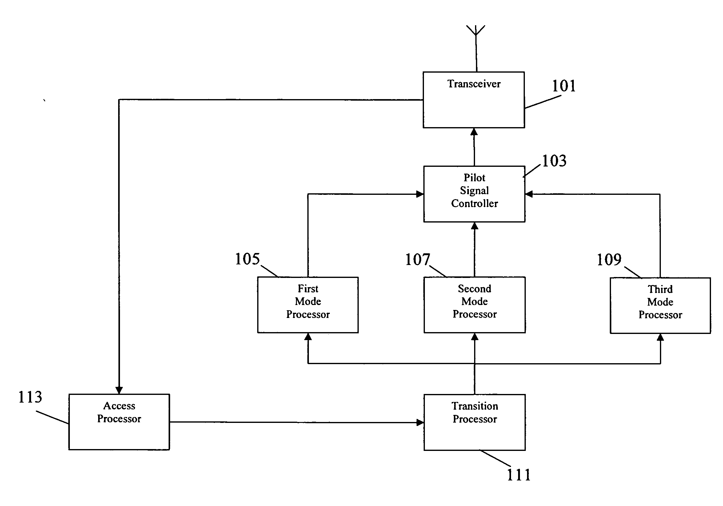
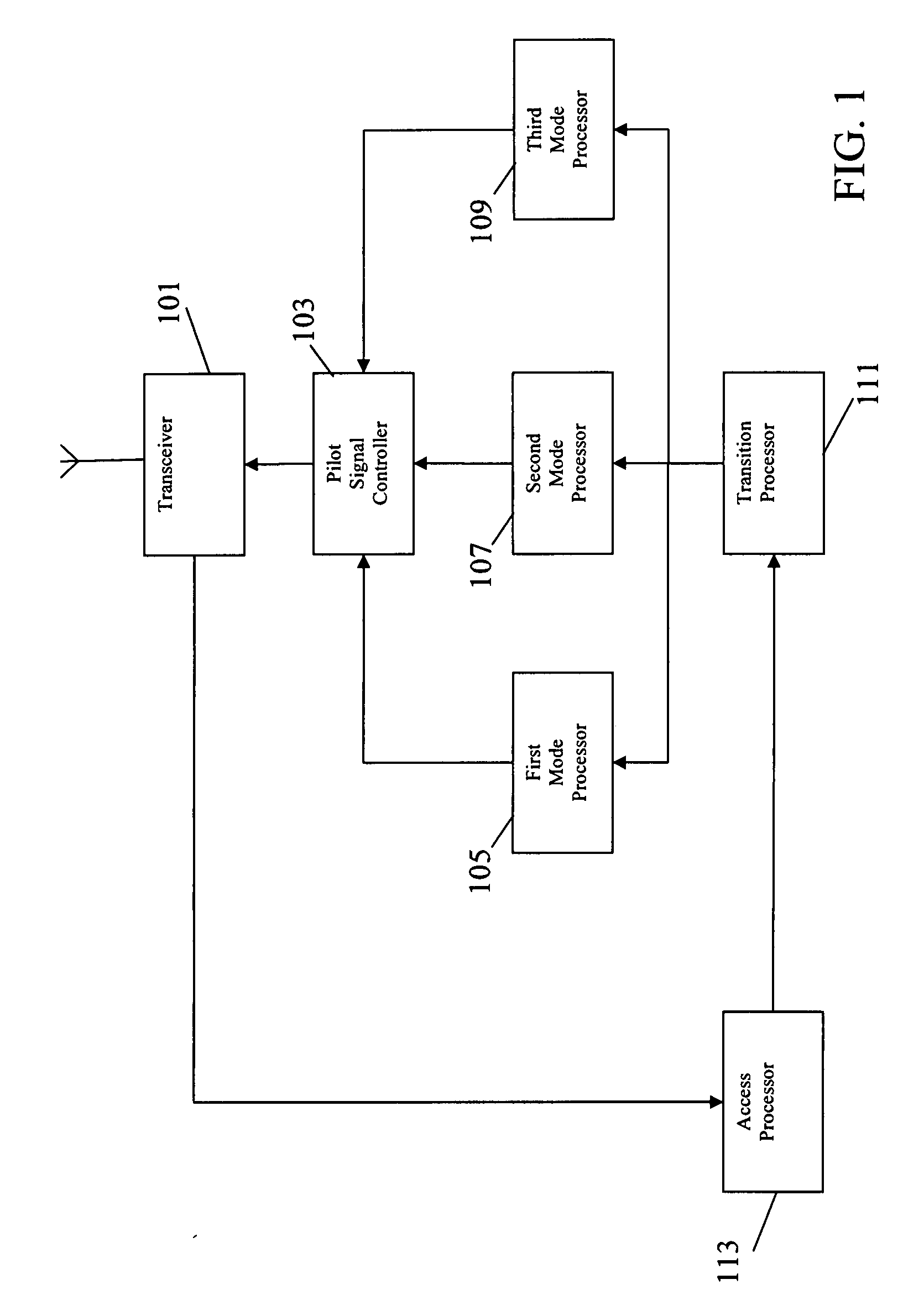
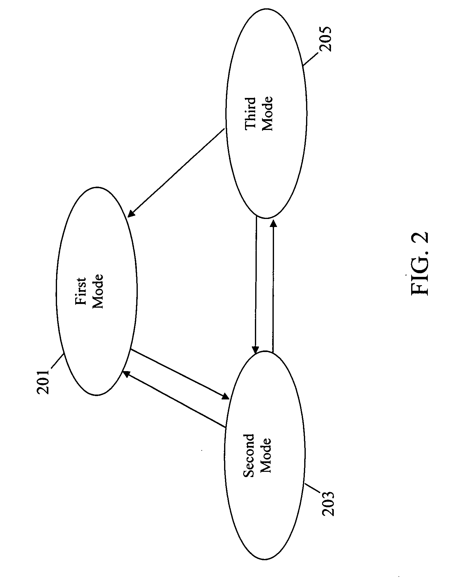
[0010]The invention may allow improved performance and specifically reduced interference and / or increased reliability. Specifically, the invention may allow the interference for pilot signal transmission to be reduced while maintaining high operational reliability by optimising the transmit power differently in different modes depending on remote station access characteristics. Specifically, the first transmit power profile may result in a temporarily varying transmit power thereby reducing the interference while, at least for some of the time, providing a transmit power sufficient to cover the whole intended coverage area for the access point. The second transmit power profile may correspond to a substantially constant pilot signal transmit power sufficient to ensure a reliable access procedure for the remote station.
[0014]The invention may allow improved performance and specifically reduced interference and / or increased reliability. Specifically, the invention may allow the interference caused by pilot signal transmissions to be reduced while maintaining high access reliability and efficient operation adapting to the current conditions during ongoing communications.

Problems solved by technology

However, a disadvantage of using pilot signals is that a relatively high level of interference is constantly generated by the pilot signals merely to support cell detection and relocation.
The generated interference is furthermore independent of the loading of the system and a substantial degree of interference is generated even by base stations not currently serving any mobile stations.
Thus, although the current approach provides a relatively simple and reliable operation it tends to introduce substantial interference and thereby reduce the capacity of the system and to potentially degrade other communications.
Indeed, in many situations, the access points will only occasionally support a communication and will typically be completely unloaded.
However, in such systems the air interface resource used by the transmission of pilot signals becomes even more significant and tends to result in inefficient systems.

Method used


Image

  • Pilot signal transmission in a radio communication system
  • Pilot signal transmission in a radio communication system
  • Pilot signal transmission in a radio communication system

Examples


Embodiment Construction

[0023]The following description focuses on embodiments of the invention applicable to an access point which is a base station of a 3rd generation cellular communication system such as UMTS. In the example, the access point is a pico-cell base station supporting one pico-cell out of a large number of pico-cells underlaying a macro cell. It will be appreciated that the invention is not limited to this application but may be applied to many other radio communication systems including for example a GSM cellular communication system or Wireless Local Area Network (WLAN).

[0024]In the specific scenario, an access point in the form of a UMTS pico-cell base station supports a very small cell of e.g. 10-50 m radius. The access point is one of many small base stations supporting similar sized pico-cells. For example, the access points may support individual flats or floors of a large block of flats.

[0025]FIG. 1 is an illustration of an access point in accordance with some embodiments of the in...


PUM


Abstract

An access point for a radio communication system transmits a pilot signal. The access point can operate in different modes with the pilot signal transmit power being controlled differently. A mode processor (105) controls a pilot signal controller (103) such that when in a first mode the access point is arranged to vary a pilot signal transmit power in accordance with a first transmit power profile. Another mode processor (107) controls the pilot signal transmit power in accordance with a second profile in a second mode. The transmit power may be constant during the second mode. A transition processor (111) is arranged to transition the access point from the first mode to the second mode in response to receiving an access request for a remote station.

Description

FIELD OF THE INVENTION[0001]The invention relates to pilot signal transmission in a radio communication system and in particular, but not exclusively, to transmissions of pilot signals in cellular communication systems such as the Global System for Mobile communication (GSM) or the Universal Mobile Telecommunication System (UMTS).BACKGROUND OF THE INVENTION[0002]Transmission of reference pilot signals is frequently used in radio communication systems. For example, in cellular systems, such as GSM or UMTS, the base stations transmit a reference or pilot signal (e.g. a beacon signal in CDMA / UMTS or a BCCH in GSM) that mobile stations use to make power measurements. These measurements can then be used directly by the mobile stations to perform cell selection and re-selection or are transmitted to the infra-structure for further processing. In essence, these measurements are used to determine the level of coverage / service that a mobile station obtains from a particular base station.[000...

Claims


Application Information

Patent Timeline
IPC IPC(8): H04B7/00
CPCH04W52/0232H04W52/143H04W52/244Y02B60/50H04W52/367H04W88/10H04W52/325Y02D30/70
Inventor VILLIER, ERIC R.LOPES, LUIS
Owner GOOGLE TECH HLDG LLC
Learn More