Ultrasonic Image Processor

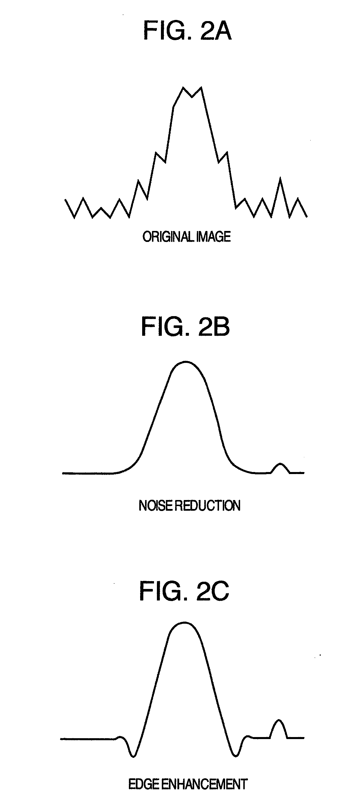
an ultrasonic imaging and processor technology, applied in image enhancement, tomography, instruments, etc., can solve the problems of loss of information derived from speckle pattern information, inability to achieve edge enhancement effect, and significant deterioration of edge components, so as to achieve noise reduction, structure enhancement processing cannot be fully reduced, and noise components enhanced

Inactive Publication Date: 2010-01-28
HITACHI MEDICAL CORP
View PDF6 Cites 42 Cited by
  • Summary
  • Abstract
  • Description
  • Claims
  • Application Information

AI Technical Summary

Benefits of technology

[0012]According to the present invention, serially performing the non-linear processing makes the edge enhancement effect and the noise reduction effect compatible with each other and the combining the composed image with the original image allows information, which has information on speckle patterns, to be retained.

Problems solved by technology

In the method exemplified in , the noises are reduced but the edge enhancement effect cannot be achieved.
Another problem with the method for reducing noises while enhancing the edge is that, when the edge is detected as noises as a result of false detection, the edge component is deteriorated significantly and information derived from speckle patterns is lost.

Method used


Image

  • Ultrasonic Image Processor
  • Ultrasonic Image Processor
  • Ultrasonic Image Processor

Examples


Embodiment Construction

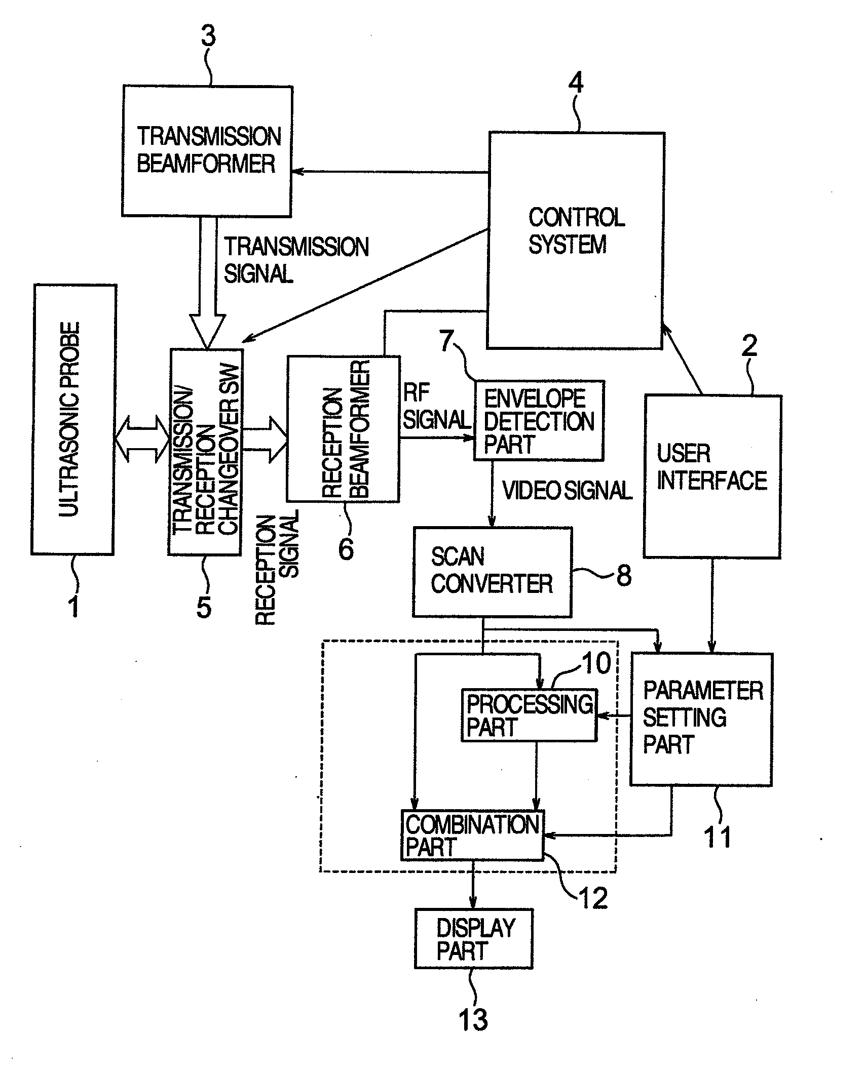
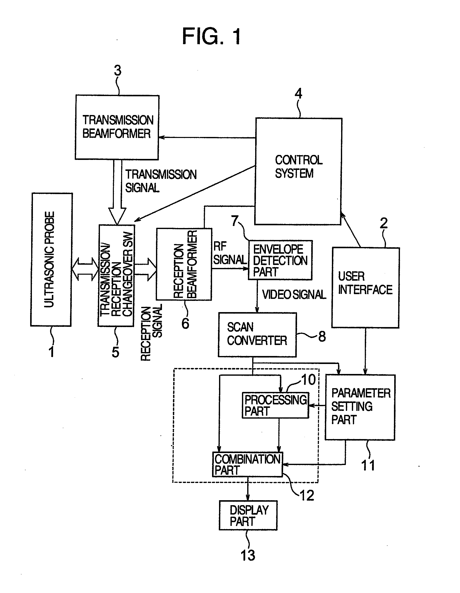
[0014]FIG. 1 shows an example of the system configuration of an ultrasonic image processing method. An ultrasonic probe 1, in which one-dimensional ultrasonic elements are arranged, transmits an ultrasonic beam (ultrasonic pulse) to a living body and receives the echo signal (reception signal) reflected from the living body. Under control of a control system 4, the transmission signal that has a delay time corresponding to the transmitter focus is output by a transmission beamformer 3 and, via a transmission / reception changeover switch 5, sent to the ultrasonic probe 1. The ultrasonic beam, which is reflected or scattered in the living body and is returned to the ultrasonic probe 1, is converted to an electrical signal by the ultrasonic probe 1 and is sent to a reception beamformer 6 via the transmission / reception changeover switch 5 as the reception signal. The reception beamformer 6, a complex beamformer that mixes the two reception signals 90 degree out of phase, performs the dyn...


PUM


Abstract

Non-linear processing is performed in which noise reduction (smoothing) is serially performed for original data to reduce high-frequency noise components, the edge enhancement processing is performed for the smoothed image and, after that, noise components are reduced again. Finally, the created image is weighted-combined with the original image.

Description

INCORPORATION BY REFERENCE[0001]The present application claims priority from Japanese patent application JP2006-1975645 filed on Jul. 20, 2006 the content of which is hereby incorporated by reference into this application.TECHNICAL FIELD[0002]The present invention relates to a technology related to an ultrasonic imaging method and an ultrasonic imaging device for ultrasound-based in vivo imaging.BACKGROUND ART[0003]An ultrasonic imaging device (B mode) used for medical diagnosis transmits ultrasounds to a living body and receives echo signals reflected from parts of the living body in which the acoustic impedance varies spatially and, based on the time difference between the transmission and the reception, estimates the position of the reflection source and converts the echo signal intensity to the brightness for imaging. It is known that specific artifacts (virtual images), called speckles, are generated in a two-dimensional ultrasonic image, and the effect of speckles must be redu...

Claims


Application Information

Patent Timeline
Patent Type & Authority Applications(United States)
IPC IPC(8): A61B8/14
CPCG01S7/52077G06T2207/30004G06T2207/10132G06T5/003G06T5/002
Inventor AZUMA, TAKASHIMASUI, HIRONARIUMEMURA, SHIN-ICHIRO
Owner HITACHI MEDICAL CORP
Why Eureka
Try Eureka