
Relating to Control of Marine Vessels

a technology for controlling marine vessels and propellers, applied in the direction of propulsive elements, steering components, position/direction control, etc., to achieve the effect of minimizing position or velocity errors

Active Publication Date: 2010-01-28
CWF HAMILTON
View PDF50 Cites 60 Cited by
  • Summary
  • Abstract
  • Description
  • Claims
  • Application Information

AI Technical Summary

Benefits of technology

[0013]a controller arranged to monitor for position or velocity deviations relative to a commanded vessel position or velocity and for heading or yaw rate deviations relative to a commanded vessel heading or yaw rate and to control the operation of the waterjet units to minimize position or velocity error and heading or yaw rate error when the dynamic control mode is enabled.
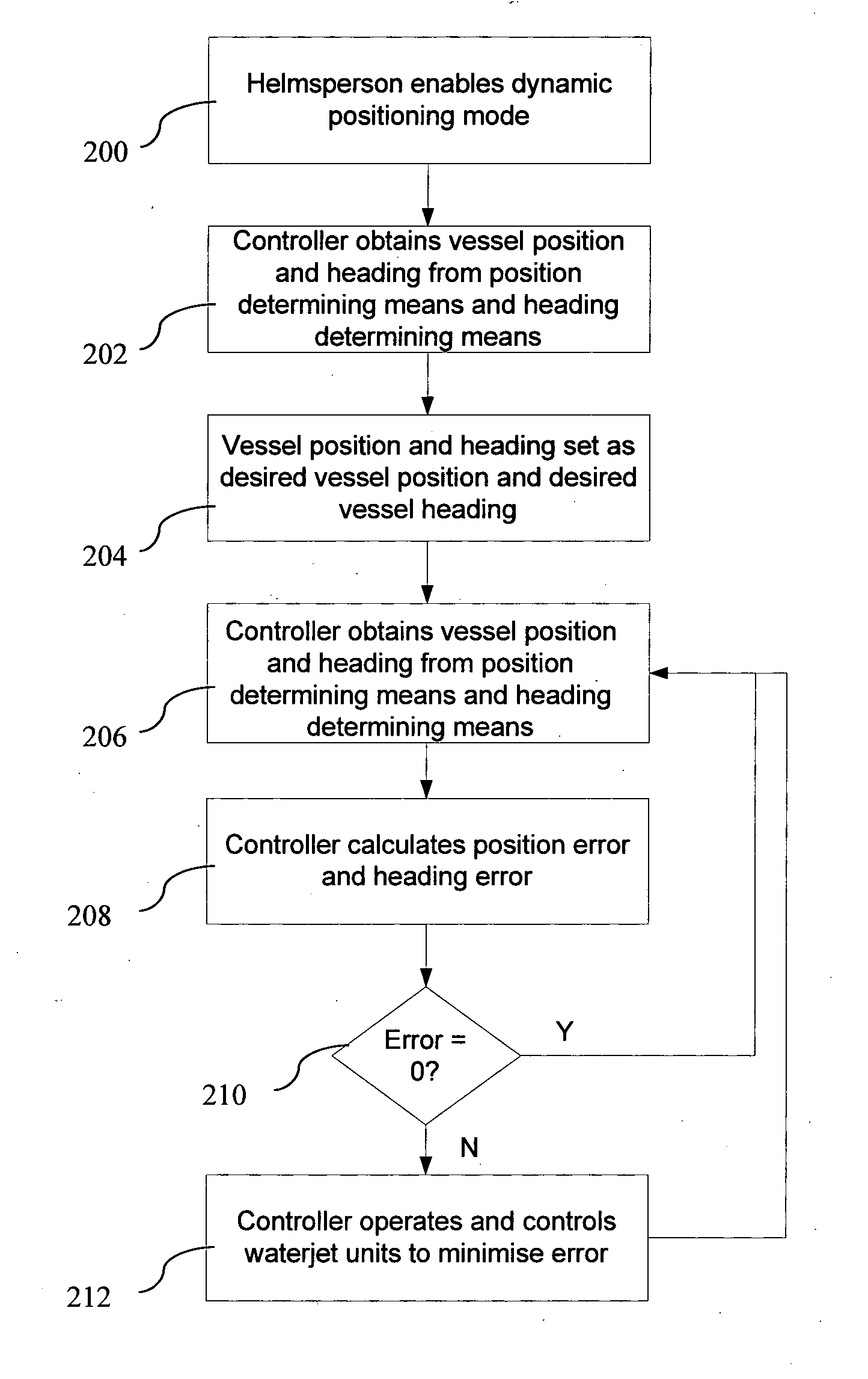
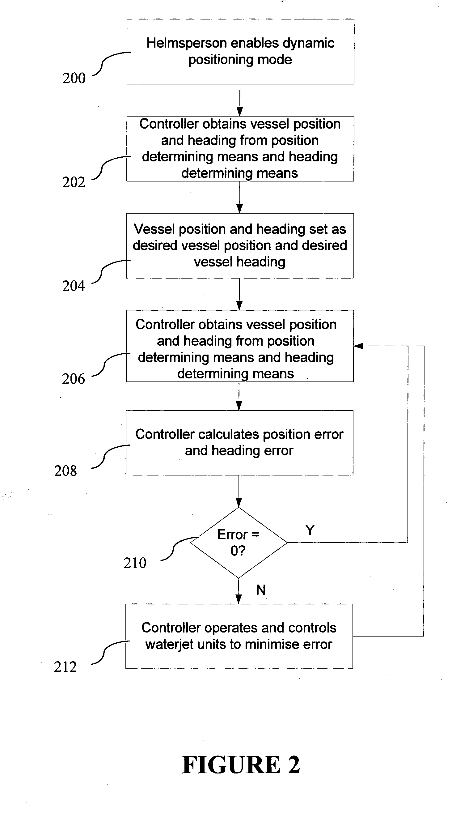
[0030](f) controlling the waterjet units to minimize the position or velocity error, and heading or yaw rate error.

Problems solved by technology

They are complex and typically utilize multiple purpose-provided drop down azimuth thrusters.

Method used


Image

  • Relating to Control of Marine Vessels
  • Relating to Control of Marine Vessels
  • Relating to Control of Marine Vessels

Examples


Embodiment Construction

[0043]The invention is now described with reference to marine vessels that are propelled with two waterjet units at the stern of the vessel (‘twin waterjet vessel’). The systems and methods of the invention may also be used on waterjet vessels propelled by more than two waterjet units, such as three or four waterjet units for example.

[0044]Dynamic Positioning System

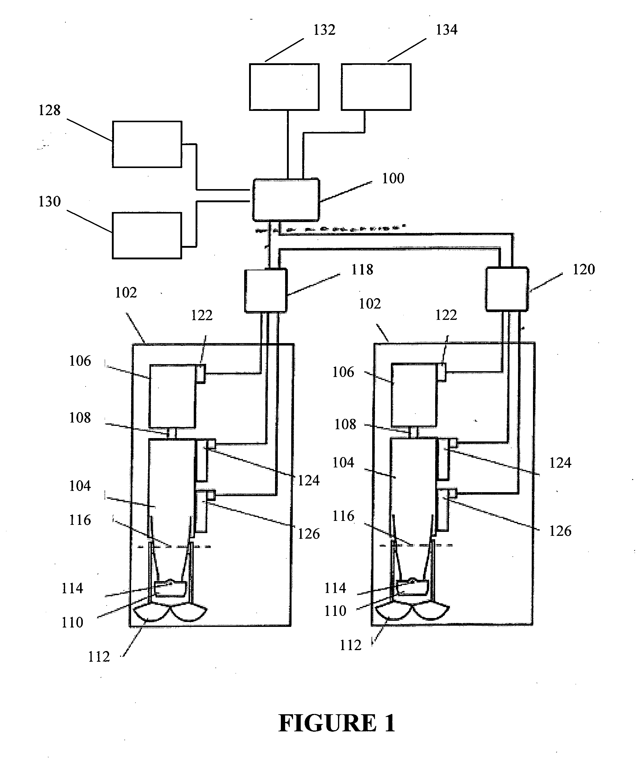
[0045]Referring to FIG. 1, a schematic arrangement of one embodiment of a dynamic positioning system of the present invention is shown. The system includes a controller 100, such as a microprocessor, microcontroller, programmable logic controller (PLC) or the like programmed to receive and process data so as to dynamically maintain the heading and position of the vessel when the dynamic positioning mode is enabled. The controller 100 may be a stand-alone or dedicated controller for dynamic positioning or preferably is incorporated into an existing vessel controller. In one form, the controller 100 is a plug-in module that...


PUM


Abstract

A dynamic control system for a marine vessel having two or more waterjet units as the primary propulsion system of the vessel, for maintaining vessel position or velocity when in a dynamic control mode, comprises a position or velocity indicator to indicate vessel position or velocity or deviations in vessel position or velocity; such as a satellite-based positioning system indicator, or accelerometers as a relative position indicator, a heading indicator to indicate vessel heading from position heading or yaw rate or deviations in vessel heading or yaw rate, such as a compass as an absolute heading indicator or a yaw rate sensor as a relative heading indicator, and a controller to control the operation of the waterjet units to substantially maintain the vessel position or velocity, and vessel heading or yaw rate when the dynamic control mode is enabled.

Description

FIELD OF THE INVENTION[0001]The invention relates to control of waterjet-propelled marine vessels and in particular, but not limited to, dynamic control of a multiple waterjet marine vessel.BACKGROUND TO THE INVENTION[0002]Dynamic positioning refers generically to an automated method of maintaining a vessel at a fixed location without mooring or anchoring the vessel. Systems are currently available that employ dynamic positioning on large vessels, such as drilling ships. These systems are typically used to maintain vessel station in deep water often for extended periods, over a fixed point on the seabed. They are complex and typically utilize multiple purpose-provided drop down azimuth thrusters.[0003]U.S. Pat. No. 5,491,636 discloses a dynamic positioning system which utilizes a steerable bow thruster, such as a trolling motor, to dynamically maintain a boat at a selected anchoring point.[0004]It is an object of the present invention to provide systems and methods that provide eith...

Claims


Application Information

Patent Timeline
Patent Type & Authority Applications(United States)
IPC IPC(8): B63H11/00G01S1/00G01S5/14B63H25/46
CPCB63H11/107B63H25/04B63J2099/006B63H2011/008B63H2025/045B63H25/46B63B79/10B63B79/40B63H11/00B63H25/00
Inventor RAE, PHILIP ANDREWBORRETT, JOHN ROBERT
Owner CWF HAMILTON
Learn More