

Sauna device
a sauna and device technology, applied in the field of sauna devices, can solve the problems of high running cost, large amount of energy required for input, and large amount of energy required in order to drive the sauna device, and achieve the effects of facilitating construction, and reducing the number of saunas
- Summary
- Abstract
- Description
- Claims
- Application Information
AI Technical Summary
Benefits of technology
Problems solved by technology
Method used
Image

Examples
embodiment 1
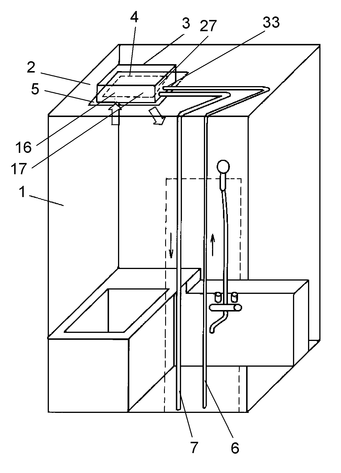
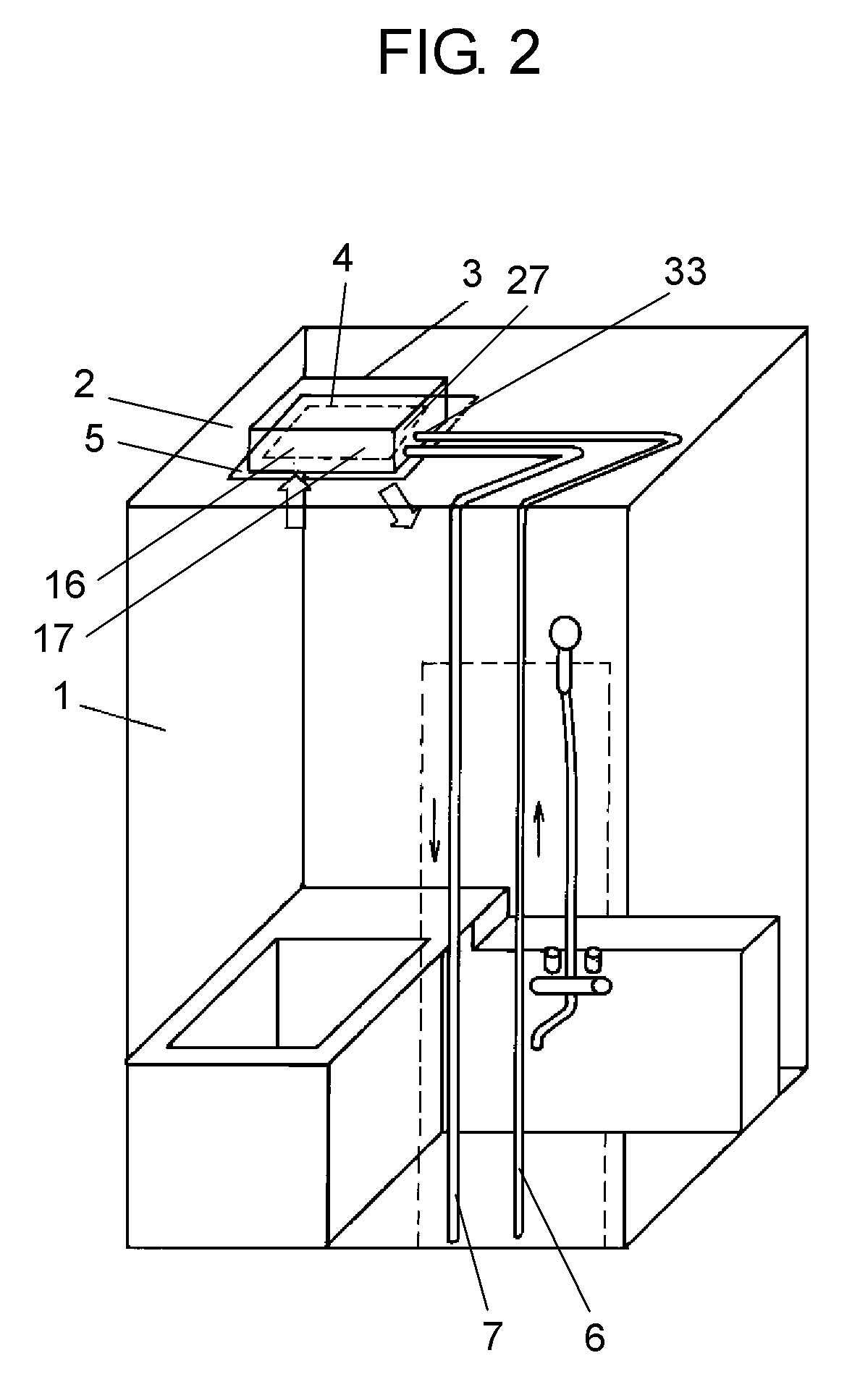
[0089]As shown in FIG. 2, device main body 3 constituting a sauna device is provided in space 2 inside the ceiling of sauna room 1 such as a bathroom. Opening 4 formed on the bottom of device main body 3 communicates with sauna room 1 through ceiling opening 5. Feed-water inlet 33 and drain outlet 27 of device main body 3 are connected with water supply pipe 6 for supplying water to device main body 3 and drainpipe 7 for draining water from device main body 3. When the inside of sauna room 1 or device main body 3 is heated and humidified, tap water is sent to device main body 3 through water supply pipe 6, a part of tap water supplied from water supply pipe 6 is used for humidification, and water not used for humidification is drained from drainpipe 7. Opening 4 has suction port 16 and blowing port 17, thereby suctioning and blowing air as indicated by the arrow.
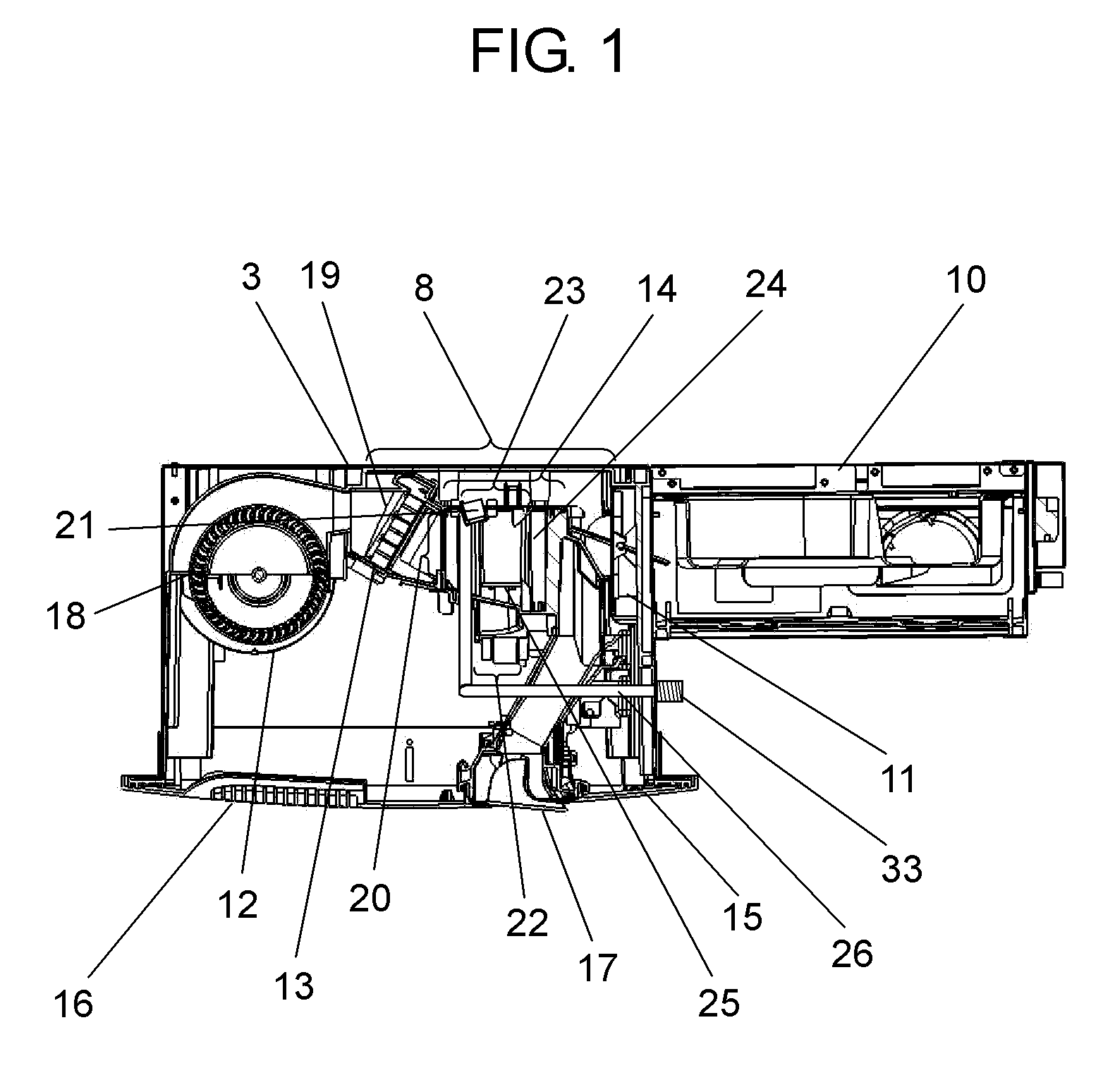
[0090]As shown in FIG. 1, device main body 3 is formed in a box shape having one opening surface. Inside, there are built-...
embodiment 2
[0102]Hereinafter, Embodiment 2 will be described. The same components as those of Embodiment 1 will be referenced by the same reference signs and numerals, and description thereof will be omitted.
[0103]As shown in FIG. 7A, heating section 13 includes electric heater 19. The air supplied by circulation blowing section 12 passes through the inside of electric heater 19, and is heated. Electric heater 19 is formed of heater element (not shown in the drawings) and thermally-conductive fin (not shown in the drawings). The thermally-conductive fin has a constant width in an air flow direction in order to effectively transfer the heat of electric heater 19 to the air flow. Thus, the air flow is rectified by the width of the thermally-conductive fin when passing electric heater 19. On the other hand, humidifying section 14 has nozzle 21 as water breakup portion 23 and injection-water impact surface 22. On the downstream side of the air flow, vapor-liquid separation unit 24 and reservoir se...
embodiment 3
[0106]The installation form of a sauna device in a sauna room is similar to that of Embodiment 1 as shown in FIG. 2. The same components as those of Embodiment 1 will be referenced by the same reference signs and numerals, and description thereof will be omitted.
[0107]FIG. 8 is a side configuration view illustrating a configuration of the sauna device of the embodiment. Here, a part for blowing air from the humidifying section to blowing port 17 is referred to as air-blowing duct 35. FIG. 9 is a schematic sectional view illustrating an air duct including air-blowing duct 35 and humidifying-section air circulation duct 20 shown in FIG. 8.
[0108]As shown in FIG. 9, bent portion 36 is not connected in a continuous curve shape but connected in a rectilinear shape in a section of the wall, and thus the noise generated from the fan motor impacts on the upper wall surface of bent portion 36, and reflects toward a side opposite to the transpiration side thereof. Hence, it becomes easy to cut...
PUM
| Property | Measurement | Unit |
|---|---|---|
| size | aaaaa | aaaaa |
| humidity | aaaaa | aaaaa |
| temperature | aaaaa | aaaaa |
Abstract
Description
Claims
Application Information