Spindle inclination detector and machine tool including the same

a technology of inclination detector and machine tool, which is applied in the direction of mechanical measurement arrangement, instruments, manufacturing tools, etc., can solve the problems of tilt and unoptimized thermal twist prevention, and achieve the effect of detecting the inclination of the spindle, low cost and more accurate distance measuremen

Inactive Publication Date: 2010-02-04
MITSUBISHI HEAVY IND LTD
View PDF7 Cites 20 Cited by
  • Summary
  • Abstract
  • Description
  • Claims
  • Application Information

AI Technical Summary

Benefits of technology

[0023]The spindle inclination detector according to the first aspect of the present invention includes: the string hanging vertically with the upper end fixed to the structure and with the lower end attached to the weight; and the distance sensor attached to the string to measure the distance to the measurement portion of the structure, or the distance sensor attached to the structure to measure the distance to the measurement portion of the string. Accordingly, if the structure is tilted by thermal deformation due to a temperature difference between portions (front and rear face plates; upper and lower face plates; or the like) of the structure to cause an inclination (tilt) of the spindle, there is a change in a relative positional relationship between the thermally deformed (tilted) structure and the vertically hanging string. Specifically, there is a change in the distance between the distance sensor attached to the string and the measurement portion of the structure or distance between the distance sensor attached to the structure and the measurement portion of the string. Such a change in distance is measured by the distance sensor. In other words, the distance measured by the distance sensor varies. It is therefore possible to detect thermal deformation (tilt) of the structure, that is, inclination (tilt) of the spindle, on the basis of the change in distance measured by the distance sensor. Accordingly, it is possible to surely detect the spindle inclination with such a simple structure at low cost.
[0024]Moreover, according to the second aspect of the present invention, the spindle inclination detector includes the non-contact gap sensor as the distance sensor. Accordingly, compared to the case of using a contact distance sensor, the distance sensor does not accidentally swing the string during the measurement of distance, thus performing more accurate distance measurement. Moreover, a commercially available gap sensor generally includes a function of canceling temperature drifts. Thus, when the gas sensor including such a function is used for the spindle inclination detector, it is possible to solve the problem of temperature drifts due to self-heating or changes in temperature.
[0025]Still moreover, according to the third aspect of the present invention, the spindle inclination detector includes the viscous fluid damper having the viscous fluid accommodated in the vessel, and the weight is put in the viscous fluid of the viscous fluid damper. Accordingly, the string and weight are less likely to be swung by external vibration or motion of the structure. Even when the string and weight are swung, such swing can be instantaneously attenuated by the viscous fluid. Therefore, the measurement of distance by the distance sensor can be performed with more accuracy.
[0026]Still moreover, in the spindle inclination detector according to the fourth aspect of the present invention, the members constituting the spindle inclination detector (the string, weight, and distance sensor; or the string, weight, distance sensor, and viscous fluid damper) are provided within the structure. Accordingly, it is possible to easily prevent these members from being interfered with an operator or a structure around the machine tool without a protection cover or the like, thus making it possible to surely detect the spindle inclination.
[0027]According to the fifth aspect of the present invention, the machine tool includes the spindle inclination detector according to any one of the first to fourth aspects of the present invention. It is therefore possible to fabricate an excellent machine tool having the effect of any one of the first to fourth aspects of the present invention.
[0028]Moreover, according to the sixth aspect of the present invention, the machine tool includes: the temperature adjustment means which adjusts temperature of the structure; and the spindle inclination correction controller which corrects the inclination of the spindle due to the thermal deformation of the structure by correcting the thermal deformation of the structure while controlling the temperature adjustment means on the basis of the distance measured by the distance sensor. Accordingly, even when the structure is tilted by the thermal deformation due to the temperature difference between the portions (front and rear face plates, upper and lower face plates, or the like) of the structure to cause an inclination (tilt) of the spindle, the spindle inclination correction controller controls the temperature adjustment means on the basis of the distance, at this time, measured by the distance sensor while correcting the thermal deformation of the structure, thus making it possible to correct the spindle inclination.

Problems solved by technology

This results in deformation of the structure, thus causing a spindle inclination (tilt).
Meanwhile, in the case of the aforementioned second means, the insulator (the thermal insulating balancing wall panel) has a thickness optimal for preventing thermal deflection, but not optimal for preventing thermal twist.

Method used


Image

  • Spindle inclination detector and machine tool including the same
  • Spindle inclination detector and machine tool including the same
  • Spindle inclination detector and machine tool including the same

Examples


embodiment 1

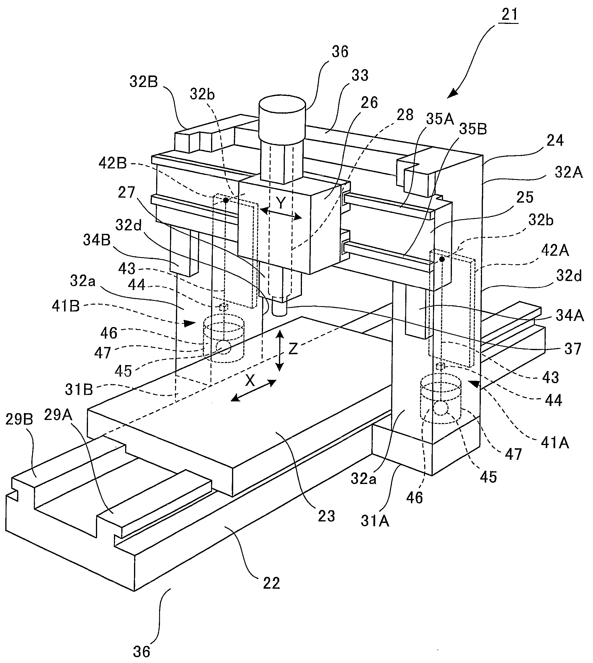
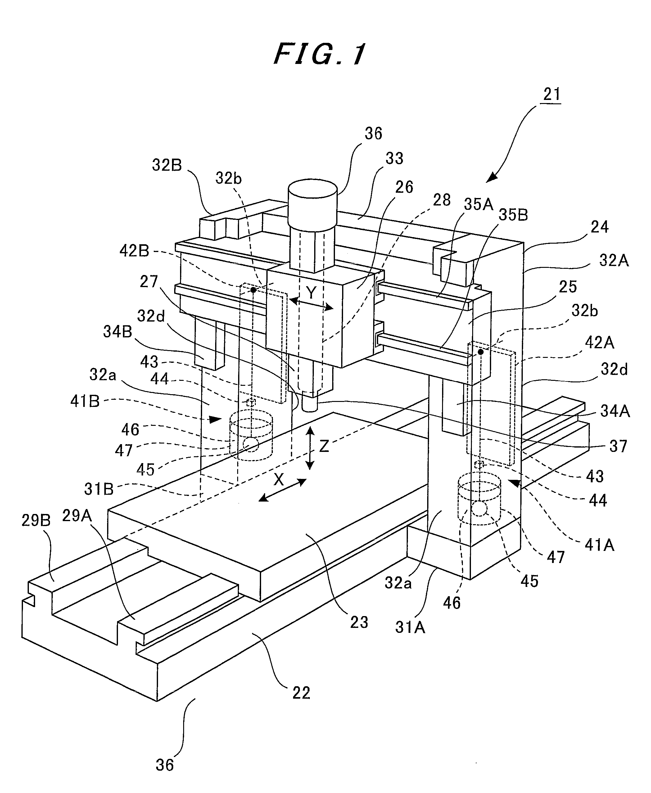
[0068]FIG. 1 is a perspective view of a machine tool according to Embodiment 1 of the present invention, and FIG. 2 is a partially cut-away side view of the machine tool.

[0069]As shown in FIGS. 1 and 2, a large-size machine tool 21 includes a bed 22, a table 23, a portal bridge 24, a cross rail 25, a saddle 26, a ram 27, and a spindle 28 as main structures.

[0070]The bed 22 is fixed to a floor surface 30. On an upper surface of the bed 22, provided are a pair of rails 29A and 29B horizontally extending in a longitudinal direction (X-axis direction) of the bed 22. The table 23 is slidably attached to the rails 29A and 29B. Accordingly, the table 23 is guided by the rails 29A and 29B to be horizontally moved in the longitudinal direction (X-axis direction) of the bed 22 by non-illustrated drive means including a feeding screw mechanism. Although omitted in the drawing, a workpiece to be machined by a tool 37 is placed on the table 23.

[0071]The portal bridge 24 is a portal one including...

embodiment 2

[0104]FIG. 3 is a partially cut-away side view of a machine tool according to Embodiment 2 of the present invention. The entire configuration of the machine tool according to Embodiment 2 shown in FIG. 3 is the same as that of the machine tool according to Embodiment 1 shown in FIGS. 1 and 2. In FIG. 3, the same parts as those in FIGS. 1 and 2 are donated by the same reference numerals.

[0105]As shown in FIG. 3, in the machine tool 21 according to Embodiment 2, two Peltier devices 42A-1 and 42A-2 are attached to the front face plates 32a and rear face plates 32d of the column 32A, respectively, and two Peltier devices 42B-1 and 42B-2 are attached to the front face plates 32a and rear face plates 32d of the column 32B (see FIG. 1), respectively, which are not shown in the drawing.

[0106]The power supply 53 of the spindle inclination correction controller 50 allows current to flow through each of the Peltier devices 42A-1, 42A-2, 42B-1, and 42B-2 in a predetermined direction on the basi...


PUM

PropertyMeasurementUnit
temperatureaaaaaaaaaa
weightaaaaaaaaaa
distanceaaaaaaaaaa

Abstract

An object of the present invention is to provide: a spindle inclination detector capable of surely detecting spindle inclination with a simple configuration; and a machine tool including the spindle inclination detector. Spindle inclination detectors (41A, 41B) are equipped in columns (32A, 32B) of a portal bridge (24) of a machine tool (21). Each spindle inclination detector includes: a string (43) which hangs vertically with an upper end fixed to the column (reinforcement (32b)) and a lower end attached to a weight (45); a gap sensor (44) which is attached to the string to measure a distance to a front face plate (32a) of the column; and an oil damper (46). Moreover, a spindle inclination correction controller provided to the machine tool controls a Peltier device (42A,42B) attached to a rear face plate (32d) of the column, on a basis of an average distance measured by the gap sensor, and thus corrects an inclination of a spindle (28) due to the thermal deformation of the column by correcting thermal deformation of the column.

Description

TECHNICAL FIELD[0001]The present invention relates to a spindle inclination detector which detects an inclination (tilt) of a spindle and a machine tool including the spindle inclination detector.BACKGROUND ART[0002]Conventional machine tools employ the following means in order to prevent reduction in machining accuracy due to thermal deformation of a structure.[0003](1) First means is to measure the temperature of a main portion of a machine tool to compensate the position of the tool tip according to a change amount in the temperature of the main portion <see Patent Document 1>[0004](2) Second means is to attach an insulator (a thermal insulating balancing wall panel) on a face plate of a structure such as a column or cross rail of a machine tool, the insulator having such a thickness that thermal equilibrium can be achieved <see Patent Document 2>[0005]Patent Document 1: Japanese Patent Application Laid-open Publication No. 2004-337996[0006]Patent Document 2: Japanese...

Claims


Application Information

Patent Timeline
Patent Type & Authority Applications(United States)
IPC IPC(8): B23Q17/00G01B3/56
CPCB23Q1/012B23Q11/0003B23Q17/22Y10T409/308288Y10T408/175Y10T409/308064Y10T29/53Y10T409/3098B23Q1/34B23Q17/00B23Q17/20
Inventor MIZUTA, KEIJIOZAWA, YOSHIHARUYOSHIKAWA, MUTSUMIKAWASHITA, RIMPEI
Owner MITSUBISHI HEAVY IND LTD
Why Eureka
Try Eureka