Method for manufacturing stereoscopic image display apparatus and stereoscopic image display apparatus

a technology of stereoscopic image and display apparatus, which is applied in the direction of color television details, electrical apparatus, instruments, etc., can solve the problems of degrading the image quality of the display image, and achieve the uniformity of the adhesive layer easily, reduce the degrading of the display image quality, and achieve sufficient quality

Inactive Publication Date: 2010-02-04
SONY CORP
View PDF66 Cites 9 Cited by
  • Summary
  • Abstract
  • Description
  • Claims
  • Application Information

AI Technical Summary

Benefits of technology

[0014]In the method for manufacturing a stereoscopic image display apparatus described above, the adhesive layer composed of a transparent gel acrylic adhesive with a thickness of 25 to 100 μm is disposed between the entire surfaces of the image display panel and the phase difference element in the bonding step of bonding the image display panel and the phase difference element. Thus, since the adhesive layer has a thickness of 25 μm or more, the uniformity of the adhesive layer is easily achieved. Since the transparent gel acrylic adhesive has a thickness of 100 μm or less, the characteristics of light that passes through the adhesive layer are not adversely affected. Furthermore, the adhesive for forming the adhesive layer has a hardness of more than 0 and 350000 μN or less. Therefore, a space between the image display panel and the phase difference element is filled with the adhesive with certainty and foreign bodies such as bubbles can be prevented from being mixed, regardless of figure tolerance or the like of the image display panel or the phase difference element. In addition, since the holding strength of the adhesive layer at 40° C. after bonding is 8 to 20 N / 20 mm, the positional accuracy between the image display panel and the phase difference element before bonding is maintained even after bonding.
[0015]According to the present invention, the entire surfaces of the image display panel and the phase difference element are bonded, a moiré phenomenon, Newton's rings (interference fringes), or the like that may degrade image quality of a display image can be prevented.
[0016]In addition, the adhesive layer for the entire bonding does not adversely affect the optical characteristics between the image display panel and the phase difference element and the positional accuracy between the image display panel and the phase difference element can be maintained even after bonding, which provides a stereoscopic image display apparatus with sufficient quality.
[0017]Since the adhesive layer composed of an adhesive is used, the cost of the adhesive itself is reduced and bonding is easily conducted, compared with the case where, for example, a glue is used. An adverse effect on environment can be suppressed compared with the case where, for example, a glue including a volatile solvent is used.
[0018]To provide a stereoscopic image display apparatus, the present invention achieves the suitable entire surface bonding between the image display panel and the phase difference element.

Problems solved by technology

The problems related to such adhesion, evenness, and the like cause a moiré phenomenon, Newton's rings (interference fringes), or the like, which may degrade image quality of a display image.

Method used


Image

  • Method for manufacturing stereoscopic image display apparatus and stereoscopic image display apparatus
  • Method for manufacturing stereoscopic image display apparatus and stereoscopic image display apparatus
  • Method for manufacturing stereoscopic image display apparatus and stereoscopic image display apparatus

Examples


Embodiment Construction

[0024]A method for manufacturing a stereoscopic image display apparatus and a stereoscopic image display apparatus according to an embodiment of the present invention will now be described with reference to drawings.

Outline Structure of Stereoscopic Image Display Apparatus

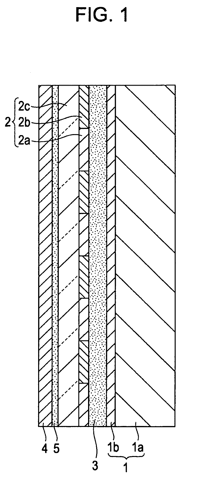
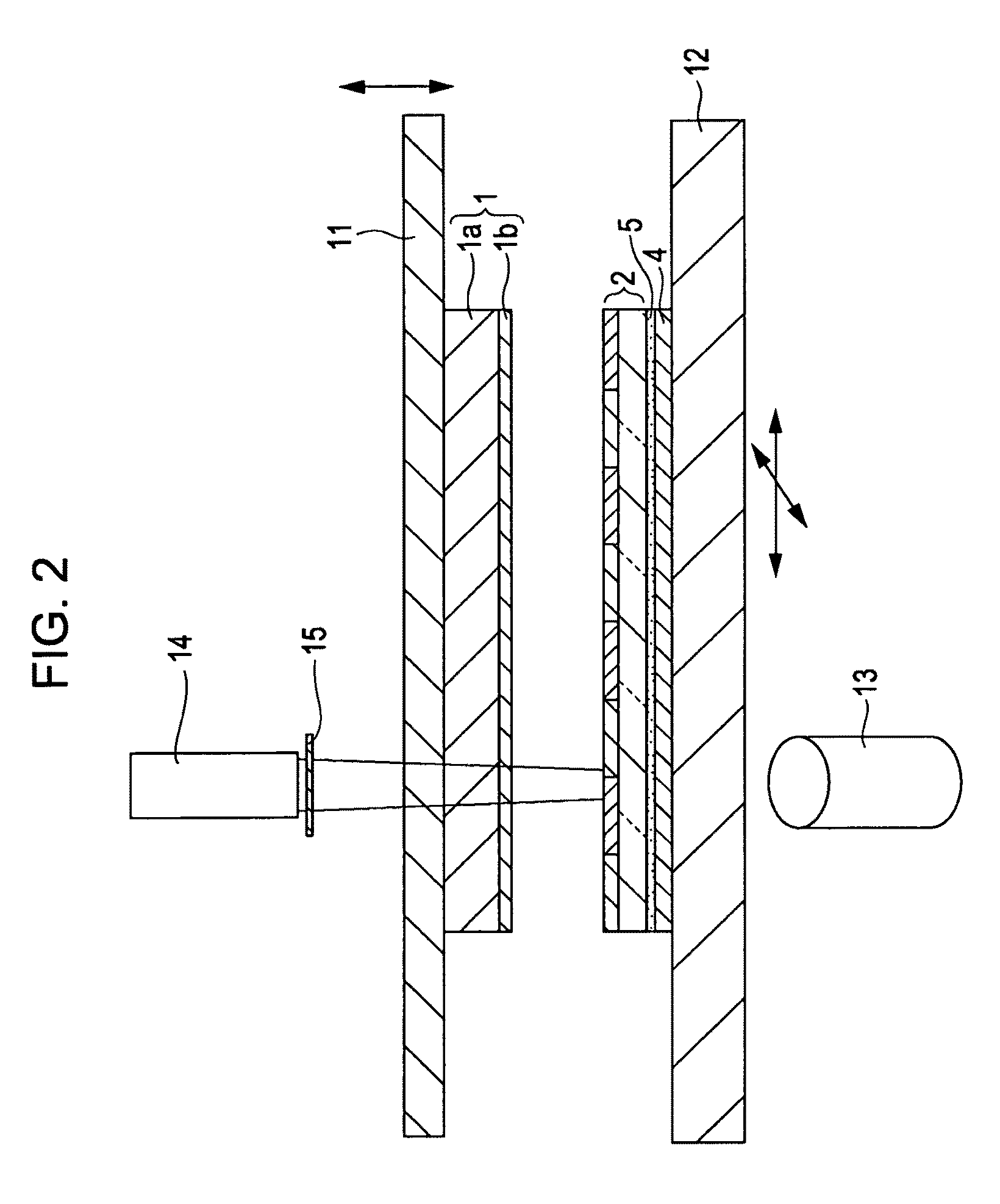
[0025]First, an outline structure of a stereoscopic image display apparatus will be described. FIG. 1 shows an example of an outline structure of a stereoscopic image display apparatus according to an embodiment of the present invention. The stereoscopic image display apparatus shown in FIG. 1 includes an image display panel 1, a phase difference element 2, an adhesive layer 3, an antireflection film 4, and a binder layer 5.

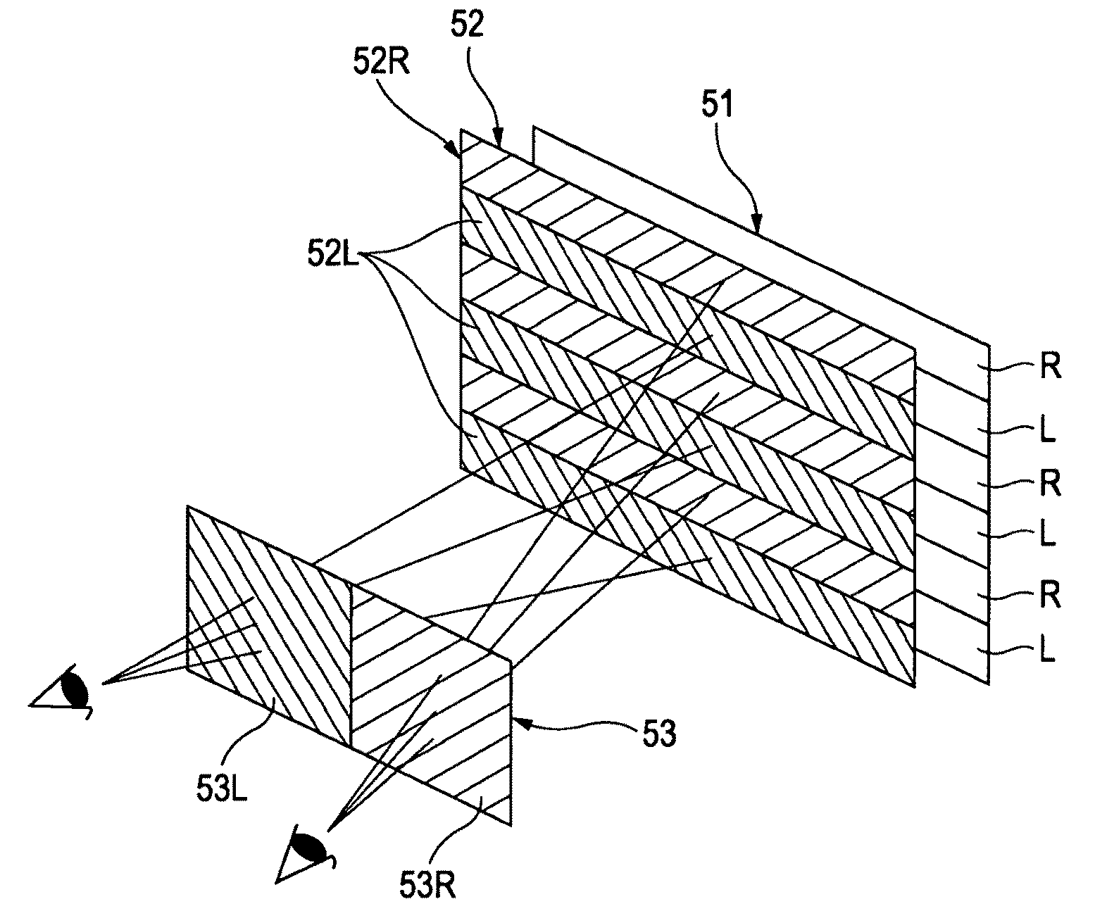
[0026]The image display panel 1 includes at least a liquid crystal panel 1a and a polarizing plate 1b disposed on the image output screen side thereof. The image display panel 1 displays a right-eye image and a left-eye image by regularly mixing them in a plane. For example, such a right-eye ima...


PUM


Abstract

A method for manufacturing a stereoscopic image display apparatus includes a bonding step of bonding an image display panel and a phase difference element by disposing an adhesive layer between the entire surfaces thereof, the image display panel displaying a right-eye image and a left-eye image by regularly mixing them in a plane, the phase difference element including a right-eye image display section corresponding to the right-eye image and a left-eye image display section corresponding to the left-eye image, the phase difference element achieving different polarizations between the right-eye image display section and the left-eye image display section, the adhesive layer being composed of a transparent gel acrylic adhesive with a thickness of 25 to 100 μm, hardness of the adhesive being more than 0 and 350000 μN or less, holding strength of the adhesive at 40° C. after bonding being 8 to 20 N/20 mm.

Description

CROSS-REFERENCE TO RELATED APPLICATION[0001]The present application claims priority from Japanese Patent Application No. JP 2008-193099 filed in the Japanese Patent Office on Jul. 28, 2008, the entire content of which is incorporated herein by reference.BACKGROUND OF THE INVENTION[0002]1. Field of the Invention[0003]The present invention relates to a method for manufacturing a stereoscopic image display apparatus that displays a stereoscopic image using a right-eye image and a left-eye image and a stereoscopic image display.[0004]2. Description of the Related Art[0005]There have been stereoscopic image display apparatuses displaying a stereoscopic image that, for example, have a structure shown in FIG. 5 (e.g., refer to Japanese Unexamined Patent Application Publication No. 2002-196281). Such a stereoscopic image display apparatus shown in the drawing includes an image display panel 51 constituted by a liquid crystal panel or the like and a phase difference element 52 disposed on th...

Claims


Application Information

Patent Timeline
Patent Type & Authority Applications(United States)
IPC IPC(8): H04N13/04H01L21/50G02B30/25
CPCG02B27/26H04N2213/001H04N13/0434G02B30/25H04N13/337
Inventor NIYOMURA, HIDEOOHNO, HIROSHIKARASAWA, JOJIHORIE, OSAMUKOBAYASHI, TAKAYUKIOKADA, MASAMICHISAKATA, ATSUSHIABE, HIROMICHI
Owner SONY CORP
Why Eureka
Try Eureka