Solid-state image pick-up device, data transmission method, and image pickup apparatus

Active Publication Date: 2010-02-04
SONY CORP
View PDF6 Cites 62 Cited by
  • Summary
  • Abstract
  • Description
  • Claims
  • Application Information

AI Technical Summary

Benefits of technology

[0008]The solid-state image pickup device described in Patent Document 1 described above performs transmission of image signals by driving differential amplifiers, the number of which is the same as that in a case where image data with a high resolution and a high frame rate is transmitted, even in a case where image signals in a low-resolution

Problems solved by technology

Thus, there is a problem in whic

Method used


Image

  • Solid-state image pick-up device, data transmission method, and image pickup apparatus
  • Solid-state image pick-up device, data transmission method, and image pickup apparatus
  • Solid-state image pick-up device, data transmission method, and image pickup apparatus

Examples


Embodiment Construction

[0026]Hereinafter, best modes for carrying out the present invention will be described in detail with reference to the drawings. In the embodiments described below, the present invention is applied, for example, to an image pickup apparatus (hereinafter, simply referred to as a video camera 1) for capturing an image of a subject by using a solid-state image pickup element.

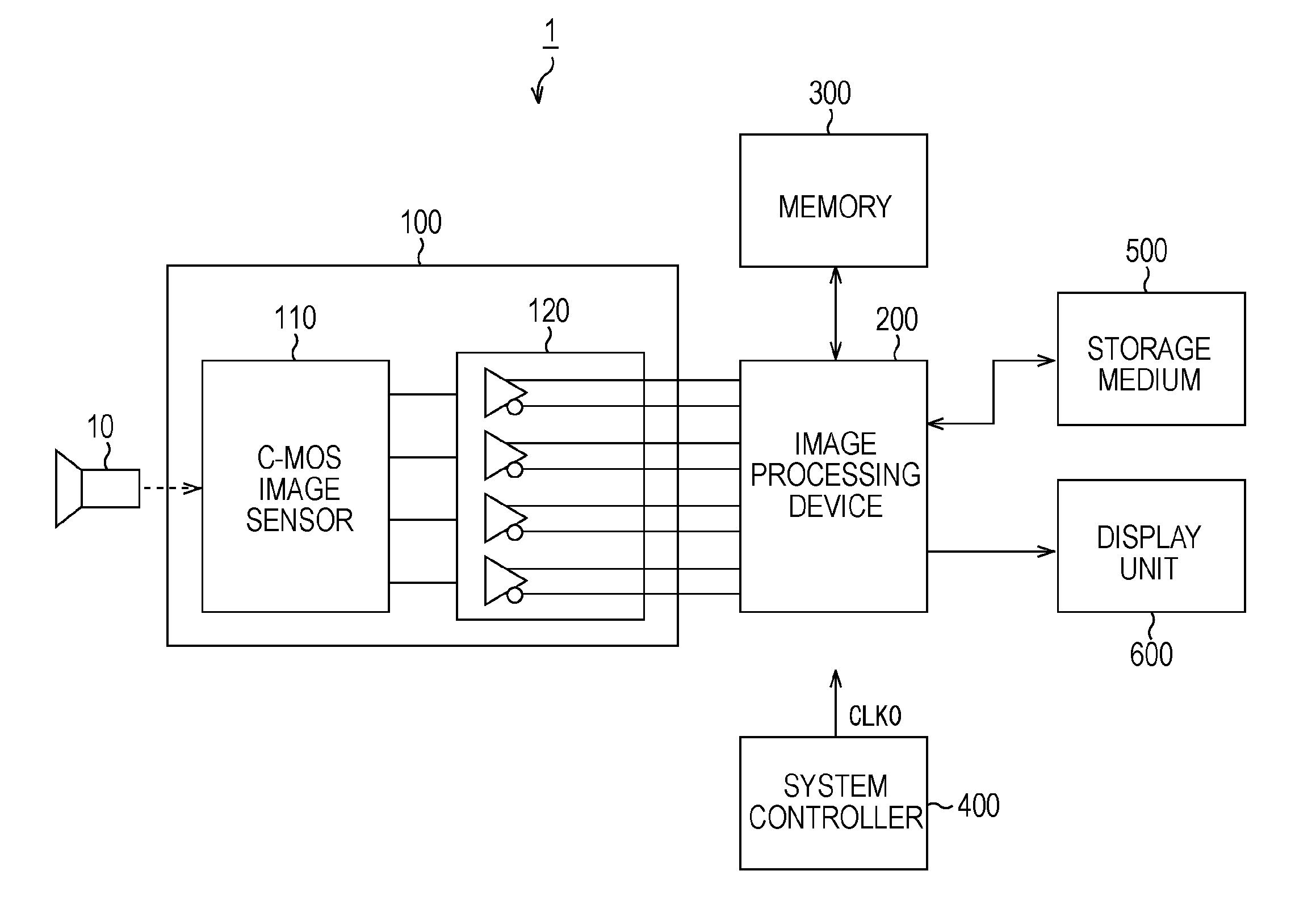
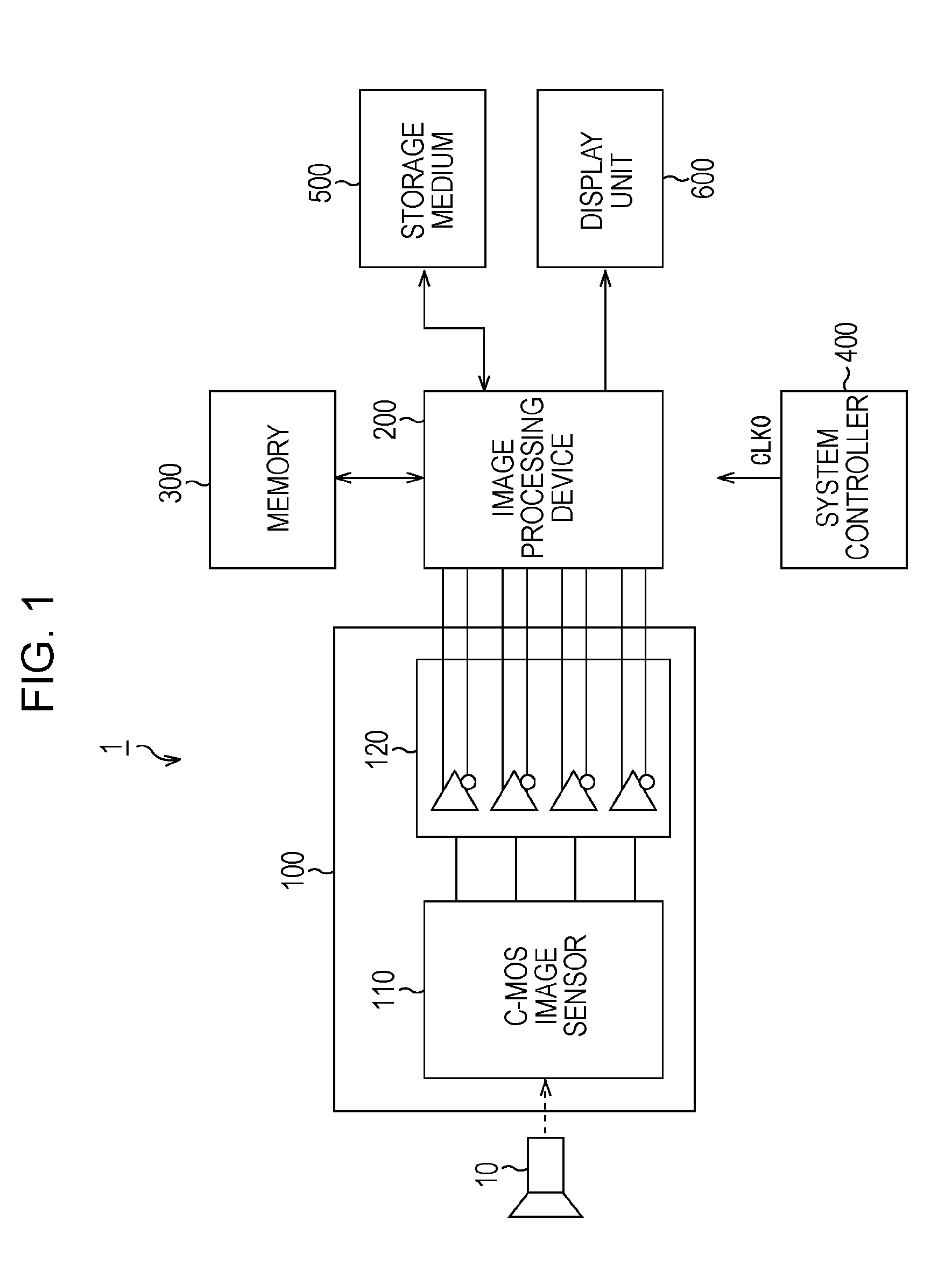
[0027]The video camera 1 includes, as shown in FIG. 1, a lens unit 10, an image pickup device 100 constituted by a C-MOS (Complementary Metal Oxide Semiconductor) image sensor 110 and a data output section 120, an image processing device 200, a memory 300, a system controller 400, a storage medium 500, and a display unit 600.

[0028]In the lens unit 10, a focus lens, a zoom lens, a diaphragm, and a driving part for driving these lenses are provided. In addition, the lens unit 10 receives light of a subject image to form the image on a light-receiving surface of the C-MOS image sensor 110.

[0029]The image pickup device...


PUM


Abstract

A video camera (100) for transmitting image data from an image pickup device to an image processing device with reduced electric power includes a C-MOS image sensor (110) that reads captured image data on the basis of a reference clock CLK0, a frequency multiplying circuit (121) that generates a high-speed clock CLK1, a rearranging circuit (122) that transposes the captured image data into bit data sequences, a data output section (120) that causes each data transmitter (124) to sequentially transmit a corresponding bit data sequence to the outside on the basis of the high-speed clock CLK1, and a system controller (400) that drives data transmitters (124), the number of which is proportional to a transmission speed.

Description

TECHNICAL FIELD[0001]The present invention relates to a solid-state image pickup device and a data transmission method for reading captured image data from a solid-state image pickup element such as a C-MOS-type image sensor and transmitting the captured image data, and further relates to an image pickup apparatus employing a solid-state image pickup element such as a C-MOS-type image sensor.[0002]The present application claims priority from Japanese Patent Application No. 2006-182030 filed Jun. 30, 2006, the content of which is hereby incorporated by reference into this application.BACKGROUND ART[0003]In recent years, image sensors based on C-MOS-type semiconductor manufacturing processes (hereinafter, referred to as C-MOS image sensors) have been widely put into practical use. A C-MOS image sensor can sequentially read pixel signals acquired from individual unit pixels 21 that are arranged two-dimensionally in, for example, m columns×n rows. Specifically, in the C-MOS image sensor...

Claims


Application Information

Patent Timeline
IPC IPC(8): H04N5/225H04N5/335H01L27/146H04L25/02H04N5/341H04N5/357H04N5/374
CPCH04L7/0008H04N5/23241H04N5/3765H04N5/374H04N5/37457H04N5/335H04N25/00H04N25/70H04N25/76H04N25/778H04N25/745H04N25/60
Inventor SHIMODA, TETSUYA
Owner SONY CORP
Why Eureka
Try Eureka