Transmitting device, receiving device, and method used in mobile communication system employing OFDM

a mobile communication system and transmitting device technology, applied in multiplex communication, power management, high-level techniques, etc., can solve the problems of reducing the amplification difficult to limit the total power level to or below the maximum allowable transmission power level, and unsatisfactory distortion of transmission signals. the effect of improving the accuracy of channel estimation and the efficiency of transmission power amplifiers

Active Publication Date: 2010-02-04
NTT DOCOMO INC
View PDF6 Cites 28 Cited by
  • Summary
  • Abstract
  • Description
  • Claims
  • Application Information

AI Technical Summary

Benefits of technology

[0008]An aspect of the present invention makes it possible to improve the accuracy of channel estimation a

Problems solved by technology

If a total power level Pall exceeds a maximum allowable transmission power level PMAX of a transmitter, undesired distortion is caused in the transmission signal.
However, while it is unknown what types of data signals are to be mapped to which subcarriers before the data signals are f

Method used


Image

  • Transmitting device, receiving device, and method used in mobile communication system employing OFDM
  • Transmitting device, receiving device, and method used in mobile communication system employing OFDM
  • Transmitting device, receiving device, and method used in mobile communication system employing OFDM

Examples


first embodiment

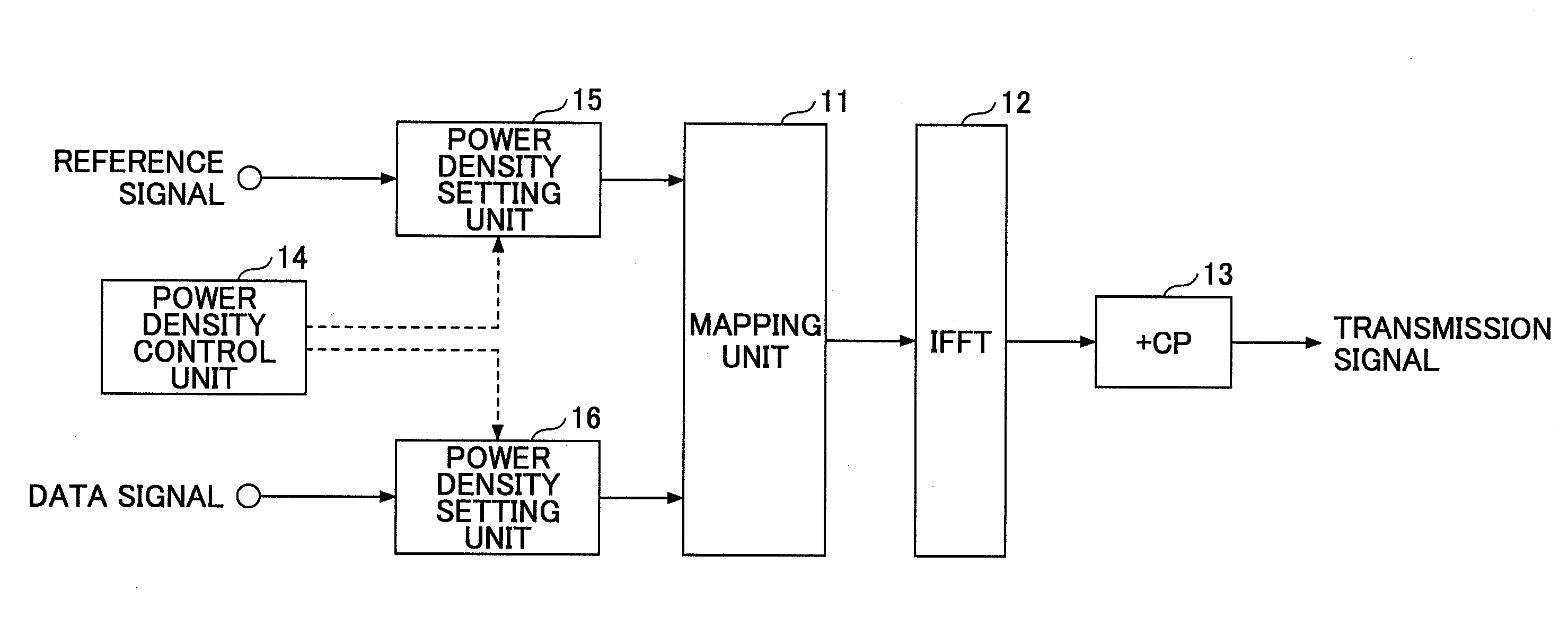
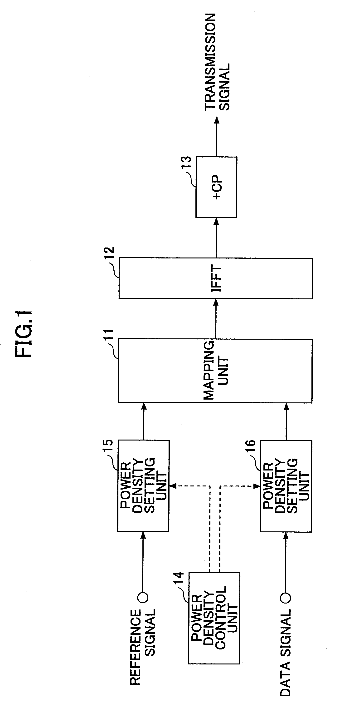
[0027]FIG. 1 is a partial block diagram of an OFDM transmitting device according to an embodiment of the present invention. Typically, the transmitting device is provided in a base station in a mobile communication system employing OFDM for downlink. Alternatively, the transmitting device may be provided in any other apparatus employing OFDM for transmission. As shown in FIG. 1, the transmitting device includes a mapping unit 11, an inverse fast Fourier transform (IFFT) unit 12, a guard interval adding unit (+CP) 13, a power density control unit 14, and power density setting units 15 and 16.

[0028]The mapping unit 11 maps power-density-adjusted reference signals and power-density-adjusted data signals to multiple subcarriers arranged along the frequency axis. Typically, signals such as reference signals and data signals are mapped to subcarriers as in FIG. 1. However, other signals such as control signals may also be mapped to subcarriers.

[0029]The inverse fast Fourier transform (IFF...

second embodiment

[0046]In the first embodiment, signals are mapped to all subcarriers and the power densities of the signals are adjusted such that the total power levels Pall of all time slots are equalized. For this reason, the power density PL of data signals in the time slots t1 and t4 is different from the power density PH of data signals in the time slots t2 and t3 (PLH). Therefore, in the first embodiment, the likelihood (likelihood information) of data signals transmitted with the power density PH is different from the likelihood (likelihood information) of data signals transmitted with the power density PL. Strictly speaking, this in turn makes it necessary to provide different sets of likelihood information for the data signals with the power density PH and the data signals with the power density PL and therefore complicates the decoding process. A second embodiment of the present invention tries to solve or reduce this problem.

[0047]FIG. 4 is a drawing illustrating adjusted power densitie...


PUM


Abstract

A transmitting device includes a transmission signal generating unit configured to generate a transmission signal by inverse-Fourier-transforming reference signals and data signals mapped to subcarriers and a transmitting unit configured to wirelessly transmit the transmission signal. In the transmitting device, a total power level allocated to signals to be transmitted in a time slot is equal to a total power level allocated to signals to be transmitted in any other time slot, and a power density per unit bandwidth of the reference signals is greater than a power density per unit bandwidth of the data signals. This configuration makes it possible to equalize the total transmission power level of all time slots and thereby to improve the power amplification efficiency. Also, with this configuration, since the reference signals are transmitted with a higher power than that for other signals, it is possible to improve the accuracy of channel estimation.

Description

TECHNICAL FIELD[0001]The present invention generally relates to mobile communication technologies. More particularly, the present invention relates to a transmitting device, a receiving device, and a method used in a mobile communication system employing orthogonal frequency division multiplexing (OFDM).BACKGROUND ART[0002]In a third generation mobile communication system such as IMT-2000, signals such as pilot signals and data signals are transmitted according to code division multiple access (CDMA). In such a communication system, pilot signals are used for channel estimation and play a central role in reception quality assurance. Therefore, pilot signals are often transmitted with a power level higher than that of other signals (power boost).[0003]Meanwhile, in a future mobile communication system succeeding the third generation system, it is planned to use a wider frequency band and to use OFDM for downlink to improve the quality, speed, and capacity of the system (see, for exam...

Claims


Application Information

Patent Timeline
IPC IPC(8): H04W72/04
CPCH04L5/0044H04L5/0051H04L5/0058Y02B60/50H04W52/325H04W52/346H04L27/2613H04L27/26134H04L27/2628H04L27/2655Y02D30/70
Inventor KISHIYAMA, YOSHIHISAHIGUCHI, KENICHISAWAHASHI, MAMORU
Owner NTT DOCOMO INC
Why Eureka
Try Eureka