Thermocouple for Gas Turbine Environments

a technology for gas turbines and thermocouples, applied in the direction of machines/engines, instruments, heat measurement, etc., can solve the problems of difficult to meet these objectives, deviation in the performance of thermocouples,

Active Publication Date: 2010-02-04
SIEMENS ENERGY INC
View PDF19 Cites 21 Cited by
  • Summary
  • Abstract
  • Description
  • Claims
  • Application Information

AI Technical Summary

Problems solved by technology

However, the harsh turbine environment encountered in these turbines along with the lack of long-term demonstrated sensor functionality, make it difficult to ...

Method used


Image

  • Thermocouple for Gas Turbine Environments
  • Thermocouple for Gas Turbine Environments
  • Thermocouple for Gas Turbine Environments

Examples


Embodiment Construction

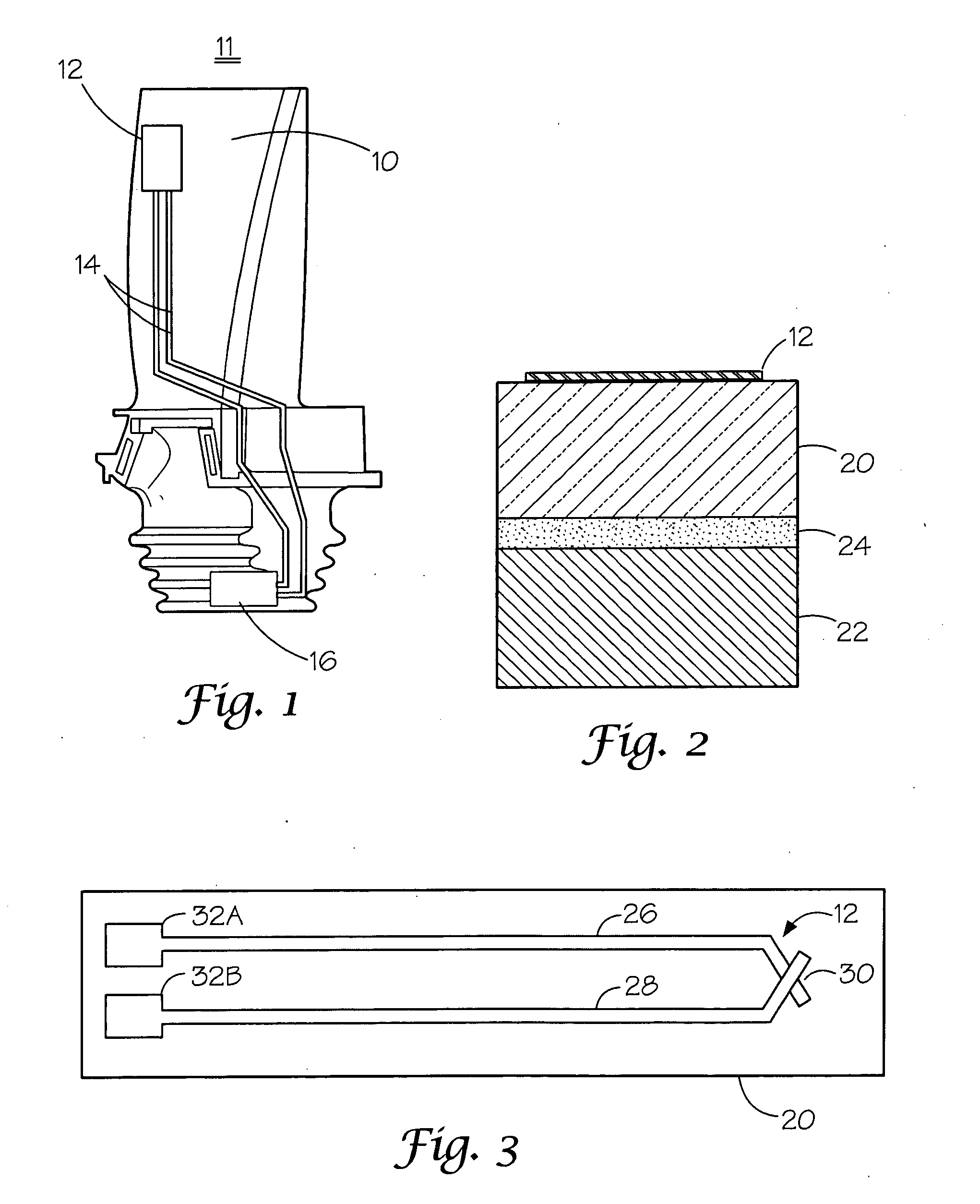
[0017]With the development of thin-film techniques it is recognized that there are several advantages of thin-film thermocouples over the standard wire thermocouples for measuring solid surface temperatures. Their low mass provides a very rapid response, the thinness of the film does not disturb the convective heat transfer characteristics of the surface compared to a wire sensor, and the small size is quite compatible with complex electronic fabrication techniques. Moreover, the low mass of the thin-film sensor, when attached to a turbine component, does not create problems with centrifugal forces placed on the thermocouple by turbine rotation. Furthermore, the thin-film sensor allows conformance to the non-planar surfaces of turbine components. Additionally, thin-film sensor implementation on critical moving components in the harsh turbine environment provides an excellent source of data for condition-based monitoring during operation. These thermocouples provide a real-time tempe...


PUM


Abstract

A thin-film thermocouple (12) is disclosed for use with a gas turbine component. The thermocouple may be formed on a non-planar substrate (22) having formed thereon an electrically insulating layer (34) capable of maintaining its insulating properties at gas turbine operating temperatures. A first thermocouple leg (26) made of pure platinum is then deposited on the dielectric layer (34). A second thermocouple leg (28) made of another pure metal or a transparent ceramic oxide is also formed on the dielectric layer (34) wherein the first and second thermocouple legs make ohmic contact at a first end of each leg to form a hot junction (30) for conversion of heat into an electrical signal. The thermocouple may be deposited on a surface of a thermal barrier coating or between a thermal barrier coating and an underlying metal substrate.

Description

[0001]This application claims benefit of the 1 Aug. 2008 filing dates of U.S. Provisional Application 61 / 085,645 and U.S. Provisional Application 61 / 085,654.FIELD OF THE INVENTION[0002]The present invention generally relates to thermocouples and their method of manufacture, and in particular to thin-film monoelemental thermoelectric elements and structure forming thermocouples that may be deposited on non-planar surfaces and are efficient at ultra high temperatures.BACKGROUND OF THE INVENTION[0003]There is an increasing demand for real-time measurement of the structural integrity of critical moving components in modern gas turbines, which operate at ultra high temperatures. Moreover, requirements for gas turbines in the future call for ever higher operating temperatures. However, the harsh turbine environment encountered in these turbines along with the lack of long-term demonstrated sensor functionality, make it difficult to meet these objectives. The materials exposed to the hot g...

Claims


Application Information

Patent Timeline
IPC IPC(8): G01K7/02
CPCF01D5/288F01D17/085G01K2217/00G01K7/04G01K2013/024G01K7/028G01K13/024
Inventor KULKARNI, ANAND A.MITCHELL, DAVID J.ROESCH, EDWARD R.
Owner SIEMENS ENERGY INC
Why Eureka
Try Eureka