Double-Sided Cutting Insert and Milling Cutter Mounting The Same

a technology of milling cutter and insert, which is applied in the direction of shaping cutter, turning machine accessories, manufacturing tools, etc., can solve the problems of long service life of cutting edges compared to a conventional milling process, inability to uniformly contact the support surface of the milling cutter, and considerable fluctuations

Inactive Publication Date: 2010-02-04
TAEGUTEC
View PDF28 Cites 13 Cited by
  • Summary
  • Abstract
  • Description
  • Claims
  • Application Information

AI Technical Summary

Problems solved by technology

That is, since the load acting in a vertical direction of the milling cutter axis is reduced as the entering angle becomes smaller, the fluctuation of the milling cutter and the impact caused thereby against cutting edges are reduced, thereby lengthening the service lives of the cutting edges compared to a conventional milling process.
In such a case, since the upper face of the cutting insert was already significantly damaged due to collision with chips during processing the workpiece, it cannot be uniformly contacted to the support surface of the milling cutter.
Thus, since the cutting insert cannot be firmly secured to the support surface of the milling cutter, considerable fluctuations can be generated during processing the workpiece.
Thus, even if other cutting edges are formed between the lower face and the flank faces of the cutting insert, when the upper face of the cutting insert is secured to the support surface of the milling cutter, the cutting edge formed at the lower face of the cutting insert cannot be contacted to the processing surface of the workpiece.

Method used


Image

  • Double-Sided Cutting Insert and Milling Cutter Mounting The Same
  • Double-Sided Cutting Insert and Milling Cutter Mounting The Same
  • Double-Sided Cutting Insert and Milling Cutter Mounting The Same

Examples


Embodiment Construction

[0027]The constitution of a cutting insert in accordance with one embodiment of the present invention will now be described with reference to the accompanying drawings.

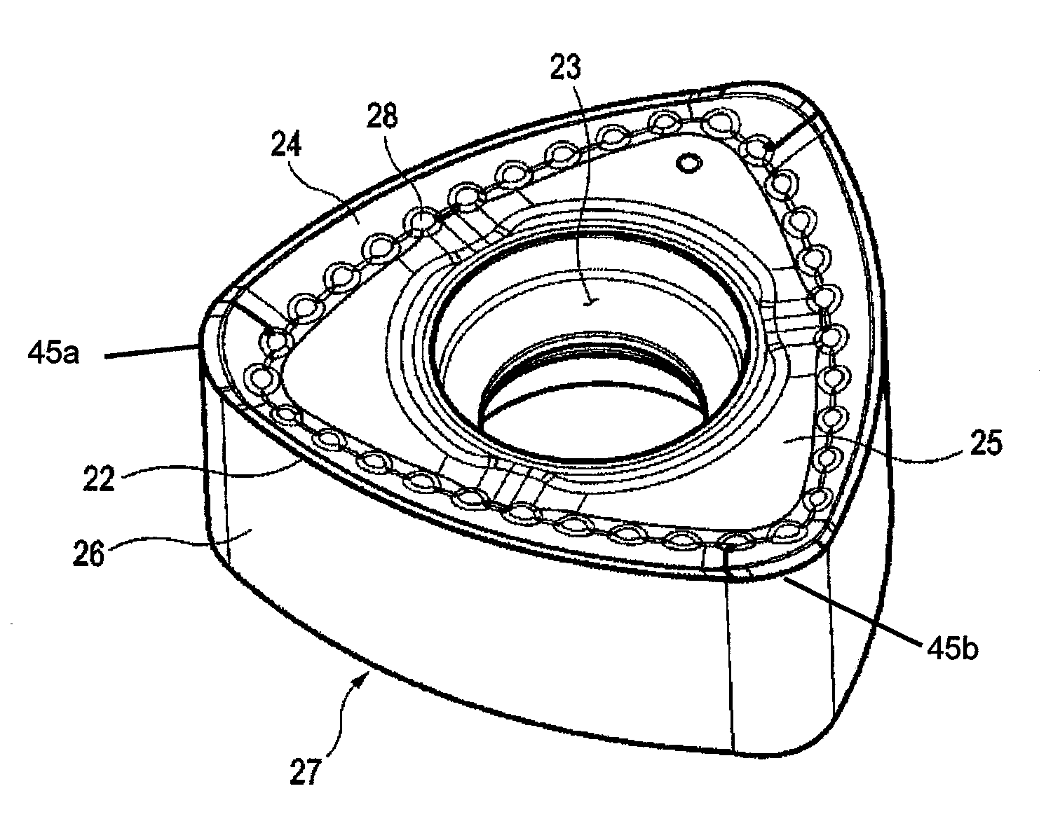
[0028]FIG. 7 is a perspective view of a double-sided cutting insert in accordance with one embodiment of the present invention. FIG. 8 is a plan view of the cutting insert. FIG. 9 is a side view of the cutting insert. FIG. 10 illustrates a milling cutter with the cutting insert mounted thereto, Referring to FIG. 7, the cutting insert 20 constructed in accordance with the present invention comprises an upper face 25, a lower face 27 and a plurality of flank faces 26. The upper face 25 of the cutting insert has a polygonal shape with curved edges. Preferably, it has a trigonal shape. The lower face 27 has a rotationally symmetrical relation to the upper face 25. The edges of the upper face 25 and the edges of the lower face 27 are connected by the flank faces 26. The edges of the upper face 25 are formed with upper cutt...


PUM

PropertyMeasurementUnit
rake angleaaaaaaaaaa
rake anglesaaaaaaaaaa

Abstract

A double-sided milling cutting insert has usable upper and lower faces. The upper face has a polygonal shape with curved edges. The lower face has a rotationally symmetrical relation to the upper face. Flank faces connect edges of the upper face to corresponding edges of the lower face. Upper cutting edges are formed on one of the edges of the upper face. The upper chip-forming portions have rake faces inclined downwardly from the upper cutting edges inwardly of the cutting insert and a plurality of protrusions arranged along inner boundaries of the rake faces for deflecting chips. When the cutting insert is mounted on the cutting tool, a width of the rake face of the upper chip-forming portion adjacent to an edge portion forming a main cutting edge gradually increases in a direction going away from a rotational axis of the cutting tool.

Description

TECHNICAL FIELD[0001]The present invention generally relates to double-sided cutting inserts, and more particularly to a double-sided cutting insert suitable for use in a milling cutter.BACKGROUND ART[0002]In milling operations, a method of cutting a workpiece by increasing a feed rate (feed distance per tooth) of a milling cutter has been recently introduced.[0003]FIGS. 1 to 3 illustrate variations of feed rates according to various entering angles. As shown in FIGS. 1 to 3, as the entering angles become smaller, a radial load transmitted from a workpiece vertically to an axis of a cutting tool (milling cutter) also becomes smaller accordingly. That is, since the load acting in a vertical direction of the milling cutter axis is reduced as the entering angle becomes smaller, the fluctuation of the milling cutter and the impact caused thereby against cutting edges are reduced, thereby lengthening the service lives of the cutting edges compared to a conventional milling process.[0004]...

Claims


Application Information

Patent Timeline
Patent Type & Authority Applications(United States)
IPC IPC(8): B23C5/20
CPCB23C5/202B23C2200/0483B23C2200/081B23C2200/203B23C2200/286Y10T407/235Y10T407/24Y10T407/2268Y10T407/1924Y10T407/192Y10T407/23B23C5/20B23C5/22B23B27/16
Inventor CHOI, CHANG HEEPARK, CHANG GYU
Owner TAEGUTEC
Why Eureka
Try Eureka