Optical Chemical Sensor Feedback Control System

Inactive Publication Date: 2010-02-11
POLESTAR TECH
View PDF9 Cites 21 Cited by
  • Summary
  • Abstract
  • Description
  • Claims
  • Application Information

AI Technical Summary

Benefits of technology

[0008]It is a further object of the present invention to provide an optical chemical sensor feedback control system which, when the system determines that the luminescent sensing film

Problems solved by technology

Although such conventional optical chemical sensors are extremely effective in monitoring various concentrations in a variety of situations, various deficiencies are encountered with the use thereof.
For example, conventional optical chemical sensors experience photobleaching over time, thereby requiring the frequent replacement or service of the sensors.
However, in conventional systems, the replacement or service of optical chemical sensors is a laborious, time consuming effort.
Moreover, depending on the nature of the system under investigation, replacement or service of the sensor may be impossible, and failure of the sensor may lead to a complete overhaul of the system, such as emptying the system of all components, cleaning the entire system thoroughly, and restarting the system from scratch.

Method used


Image

  • Optical Chemical Sensor Feedback Control System
  • Optical Chemical Sensor Feedback Control System
  • Optical Chemical Sensor Feedback Control System

Examples


Embodiment Construction

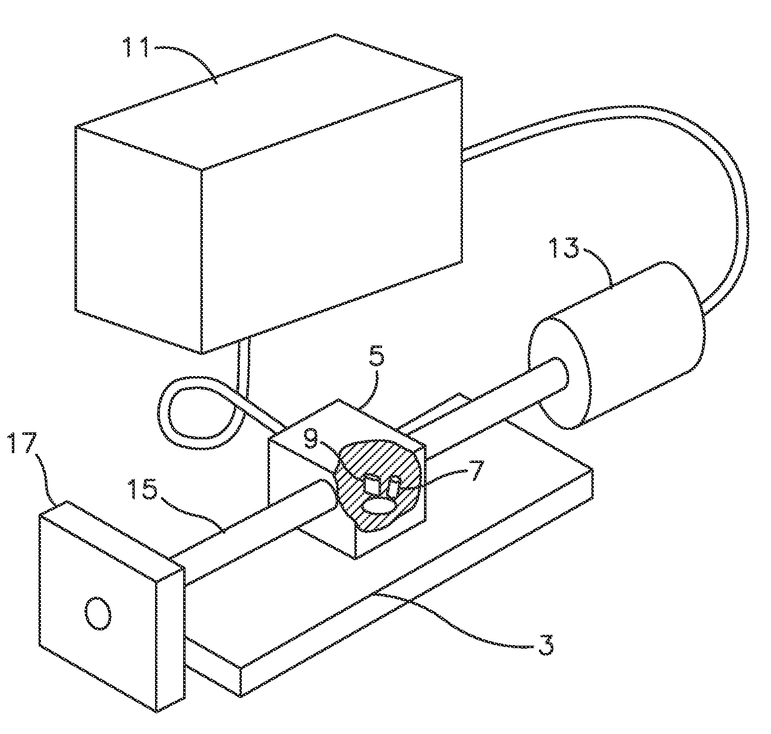
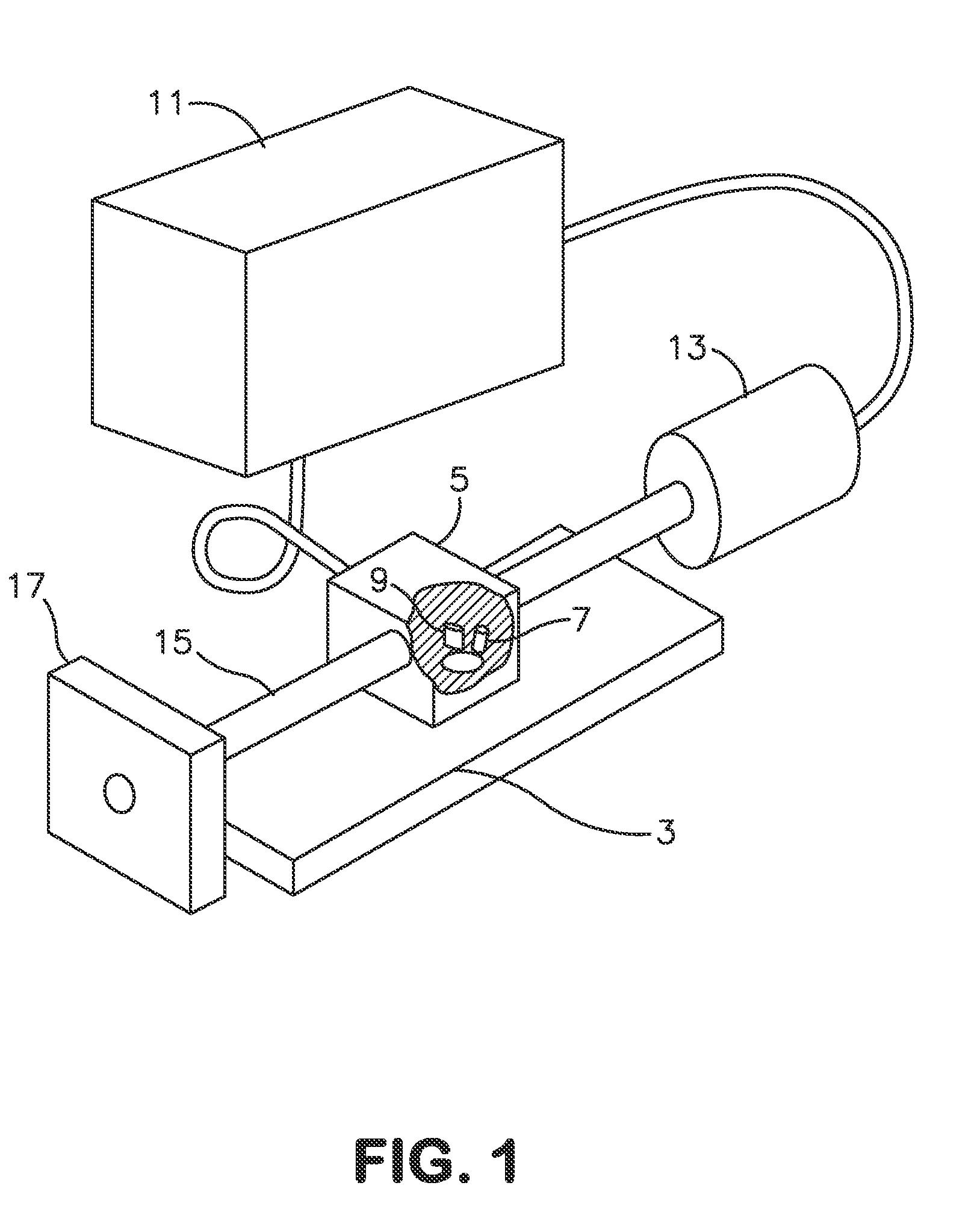
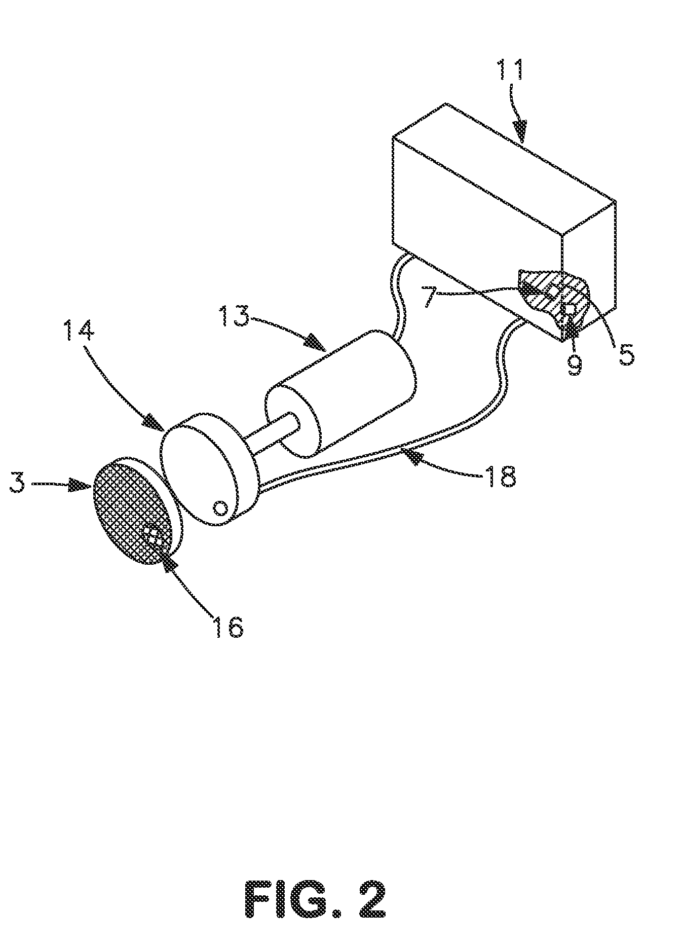
[0038]As mentioned above, many conventional feedback control systems utilize fluorescence lifetime-based optical sensors to monitor the concentration of a variety of chemical constituents, such as molecular O2, pH and carbon dioxide. These optical sensors contain sensing membrane(s) which need replacement and / or servicing on a regular basis. In order to overcome this problem, the optical chemical sensor feedback control system 1 of the present invention allows a user thereof to monitor the status (condition) of the sensing film, and adjust the magnitude of photoexcitation thereof to compensate for degradation in the responsiveness of the film over time.

[0039]In addition, the system is operable to enable a user to conveniently exchange the sensing membrane with a fresh sensing film 3 or, alternatively, move the optical interrogation system (referred to herein as the optical processor 5) adjacent to a section of the sensing membrane that has not been adversely affected by overuse or e...


PUM


Abstract

An optical chemical sensor feedback control system is provided comprised of a luminescent sensing film, an optical processor adjacent the sensing film capable of sinusoidally photoexciting the luminescent sensing film and detecting the luminescent emission resulting therefrom, and a computer control means executing a computer program, in communication with the optical processor. The computer control means is operable to control the magnitude of the photoexcitation of the luminescent sensing film, wherein the computer control means receives data regarding the luminescent emission resulting therefrom, analyzes same, and determines the magnitude and phase shift of the luminescence relative to the photoexcitation. Further, the system herein is operable to determine the status of the sensing film, and adjust the magnitude of photoexcitation thereof based on same. In addition, the system, via the optical processor positioning means, is operable to adjust the physical position of the optical processor and / or light source in relation to the sensing film, based on data received from the computer control means.

Description

CROSS-REFERENCE TO A RELATED APPLICATION[0001]This application is a continuation-in-part application of copending application Ser. No. 11 / 113,464, filed Apr. 25, 2005, the contents of which are incorporated herein by reference.FIELD OF THE INVENTION[0002]An optical chemical sensor feedback control system for controlling optical sensing systems utilizing phase-sensitive fluorescence lifetime measurement in the detection process is provided. In particular, an optical chemical sensor feedback control system is provided which measures the luminescent emission of sensing films with respect to the level of photoexcitation thereof, monitors the status of the sensing film over time, adjusts the magnitude of the sensing film based on same (to, for example, compensate for photobleaching), and adjusts and / or replaces sensors (i.e., sensing films) in the system as needed.BACKGROUND OF THE INVENTION[0003]Optical chemical sensors have been developed for monitoring the concentration of a variety o...

Claims


Application Information

Patent Timeline
IPC IPC(8): H01L31/14G01J1/58G01J1/20
CPCG01N21/6408G01N2201/062G01N2021/6484G01N21/643
Inventor KANE, JAMES A.
Owner POLESTAR TECH
Why Eureka
Try Eureka