Fluid Control

a technology of fluid pressure and control, which is applied in the direction of manufacturing tools, welding equipment, other domestic objects, etc., can solve the problems of pressure drop across the flowpath, and achieve the effects of reducing erosion, reducing erosion and reducing pressure within the vortex chamber

Active Publication Date: 2010-02-11
IMI VISION LTD
View PDF5 Cites 1 Cited by
  • Summary
  • Abstract
  • Description
  • Claims
  • Application Information

AI Technical Summary

Benefits of technology

[0010]As the fluid flows mutually impinge, particles in each fluid flow give up a large amount of their energy as they decelerate and then accelerate as they enter a flow in a different direction. The reduced energy of individual particles results in reduced erosion of the walls of the flowpath should they impinge thereon.
[0012]Preferably the three substantially tangential inlet passages to the vortex chamber are offset by an amount x along the radius of the vortex chamber towards said substantially axial outlet. By offsetting the inlet passages in this manner the fluid entering the vortex chamber via each inlet passage will impinge directly on the flow entering the vortex chamber via the next inlet passage without the flow first impinging on the walls of the vortex chamber, thus further reducing erosion
[0013]Preferably the at least three inlet passages have a substantially 90 degrees bend upstream of the vortex chamber. The 90 degree bend creates a resistance to flow and by placing one inline in the inlet passage prior to the vortex chamber the pressure within the vortex chamber is further reduced thereby further decreasing erosion within the vortex chamber.
[0020]Preferably the inner tubular element is of a ceramic material, as used herein the term ceramic includes not only traditional inorganic non-metallic ceramics but also inorganic metallic materials, for example metal compound ceramics. Ceramic materials are particularly suitable as they can be very hard and have good wear properties. Preferably the ceramic material is a metal compound ceramic, for example a metal boride, nitride or carbide. Particularly suitable are tungsten carbides and aluminum magnesium borides. Alternatively the trim may be of an inorganic non-metallic ceramics material of a suitable hardness, for example silicon nitride or zirconium, in particular partially stabilized zirconium. The ceramic may comprise a single compound or a mixture of substances, for example a particular ceramic may be mixed with, or doped with, an element or compound to increase the wear characteristics of that ceramic, for example a Group 3, 4 or 5 elements or a nitride or boride thereof may be added. In particular TiB2 may be used to increase the wear characteristics.
[0029]allowing the outer element to cool and contract around the inner element thereby creating an interference fit between the two elements and thus joining them together.
[0036]allowing the inner sleeve warm and expand thereby creating an interference fit between the two elements and thus joining them together.

Problems solved by technology

The vortex has a lower pressure at its centre and it is in the lower pressure area of the vortex that the fluid flow exits resulting in a pressure drop across the flowpaths.

Method used


Image

  • Fluid Control
  • Fluid Control
  • Fluid Control

Examples


Embodiment Construction

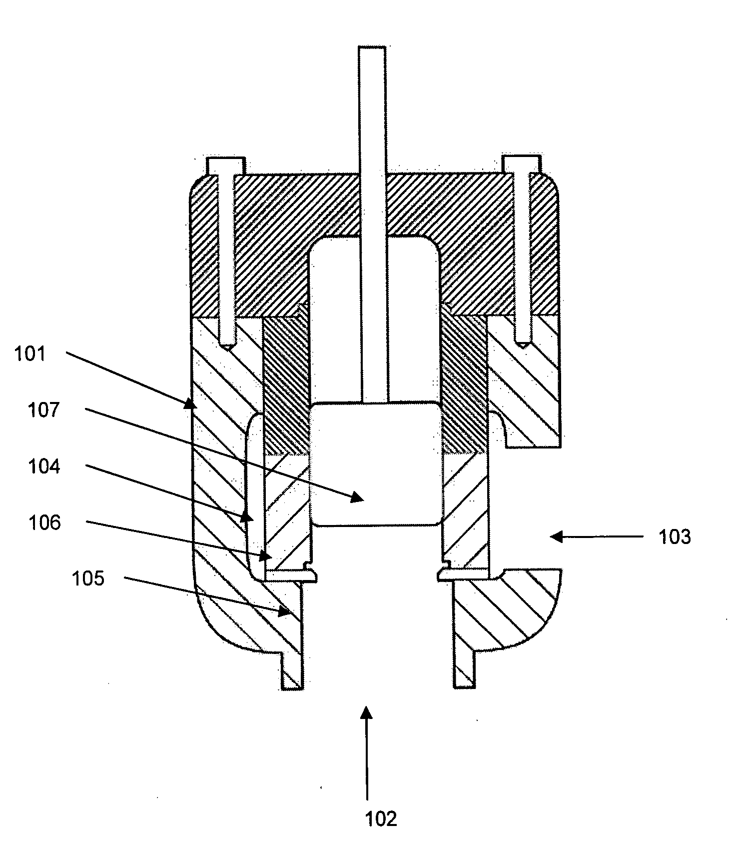
[0047]Referring to FIG. 1 an example of a valve trim in a fluid control valve is shown as common in the art comprising a valve body 101 with a inlet 102 and outlet 103 in fluid communication with one another via a central chamber 104 containing seat ring 105, valve trim 106 and plug 107. When the valve plug 107 sits on the valve seat ring 105 no flow is permitted to pass through the valve. As the plug 107 is lifted in a controlled movement, flow is allowed to enter the valve through inlet 102 and passes through the valve trim 106, which reduces the fluid pressure, and out of outlet 103.

[0048]The trim 106 has a plurality of flowpaths therethrough which have a resistance to flow. The flow direction shown in this valve is known as over the plug flow and the invention will be described in relation to such a flow direction. Flow direction in the opposite direction, i.e. flow enters at 103 and exits at 102 is known as under the plug flow and the invention is equally applicable to such a f...


PUM

PropertyMeasurementUnit
flow resistanceaaaaaaaaaa
radiusaaaaaaaaaa
resistanceaaaaaaaaaa

Abstract

A valve having a trim comprising a plurality of a vortex flowpaths, each flowpath comprising a central vortex chamber and having three tangential inlet passages is provided. As the fluid flows through the inlet passages and enters the vortex chamber the flows start to turn and impinge upon one another, i.e., the flow entering via inlet passage will impinge upon the flow entering via inlet, the flow entering inlet will impinge on the flow entering inlet and the flow entering inlet will impinge on the flow entering inlet. As the flow entering vortex chamber impinges on another fluid flow as opposed to a wall of the flowpath the vortex can be used to create a flowpath with reduced erosion. The flow from the inlets combine in a radial flow within the vortex chamber and exit via the outlet which is substantially axial to the vortex chamber.

Description

CROSS-REFERENCE TO RELATED APPLICATIONS[0001]The present application claims priority to International Application No. PCT / GB2007 / 003512 which was filed on Sep. 14, 2007 and claims priority to Great Britain Patent Application No. 0618165.5 filed on Sep. 15, 2006.STATEMENT REFederally Sponsored Research / Development[0002]Not ApplicableBACKGROUND OF THE INVENTION[0003]1. Technical Field of the Invention[0004]This invention relates to the control and reduction of fluid pressure in valves for controlling fluid flow, especially but not exclusively severe service valves for use in power industries and oil and gas wells.[0005]2. Description of the Related Art[0006]The technology most widely used in severe service valves utilizes pressure letdown chambers consisting of one or more flow passages containing multiple orifice openings, labyrinths, or multiple, abrupt angular turn, passageways resulting in a staged pressure reduction. Alternatively, flow restrictions can be afforded by providing i...

Claims


Application Information

Patent Timeline
Patent Type & Authority Applications(United States)
IPC IPC(8): F16K47/08B21K1/20
CPCF16K25/04Y10T29/49405F16K47/08Y10T137/86759F16L55/027
Inventor STEPANOV, EUGENE V.GOULET, DOUGLAS P.HUNTER, JOHN
Owner IMI VISION LTD
Why Eureka
Try Eureka