Method and apparatus for repairing a core spray downcomer pipe slip joint coupling

a technology of slip joint coupling and core spray, which is applied in the direction of nuclear engineering, greenhouse gas reduction, nuclear elements, etc., can solve the problems of intergranular stress corrosion cracking of the original core spray system piping

Active Publication Date: 2010-02-11
GE HITACHI NUCLEAR ENERGY AMERICAS
View PDF19 Cites 12 Cited by
  • Summary
  • Abstract
  • Description
  • Claims
  • Application Information

AI Technical Summary

Benefits of technology

[0006]In another exemplary embodiment of the invention, a clamping device for supporting or structurally replacing a cracked weld between connected pipes in a core spray line in a boiling water nuclear reactor comprises a primary clamp housing including a first curved portion, a secondary clamp housing including a second curved portion, a hinge assembly rotationally joining together the primary and secondary clamp housings, at least one coupling bolt and at least one coupling bolt keeper nut connecting the primary and secondary clamp housings together so as to secure the primary and secondary clamp housings on opposite sides of the spray line connected pipes in facing relation, the at least one coupling bolt extending through extensions of the connected primary and secondary clamp housings, at least one first lateral pin inserted into the first curved portion of the primary clamp housing, a distal end of the at least one first lateral pin seating into a first conical hole machined in the spray line connected pipes, at least one first lateral pin keeper positioned on the primary clamp housing engaging the at least one first lateral pin, at least one second lateral pin inserted into the second curved portion of the secondary clamp housing, a distal end of the at least one second lateral pin seating into a second hole machined in the spray line connected pipes, and at least one second lateral pin keeper positioned on the secondary clamp housing engaging the at least one second lateral pin, the first and second lateral pins each including ratchet teeth that interface with corresponding teeth of the first and second lateral pin keepers, respectively, to prevent rotation of the first and second lateral pins to thereby retain preloads on the first and second lateral pins.

Problems solved by technology

The welds in the original core spray system piping are susceptible to Intergranular Stress Corrosion Cracking (IGSCC).

Method used


Image

  • Method and apparatus for repairing a core spray downcomer pipe slip joint coupling
  • Method and apparatus for repairing a core spray downcomer pipe slip joint coupling
  • Method and apparatus for repairing a core spray downcomer pipe slip joint coupling

Examples


Embodiment Construction

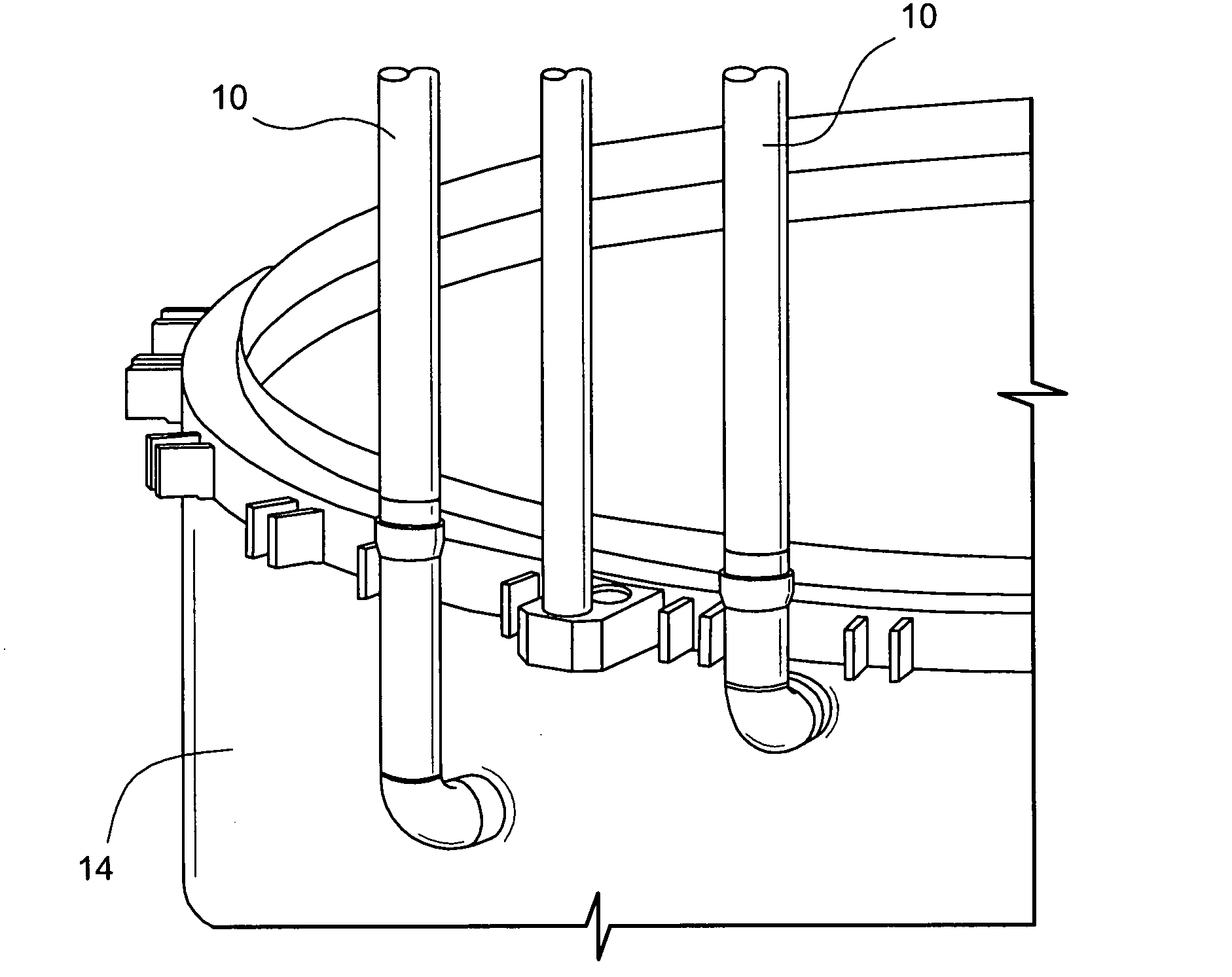
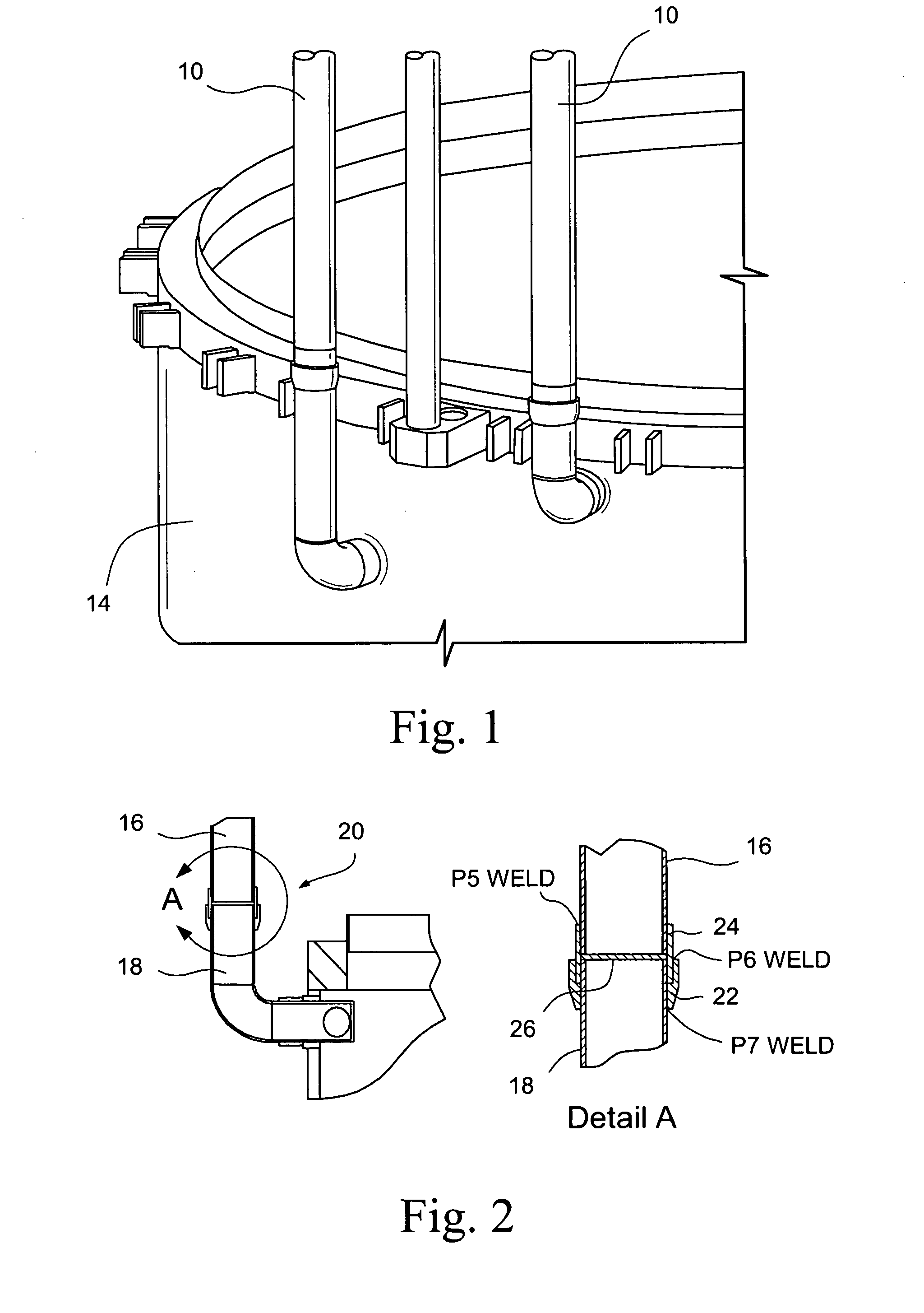
[0027]The present invention is directed to a clamp, which structurally replaces cracked core spray downcomer slip joint welds. More specifically, the present invention is directed to a slip joint clamp for repairing cracked downcomer slip joint welds in Boiling Water Reactor plants with varying sized downcomer pipes.

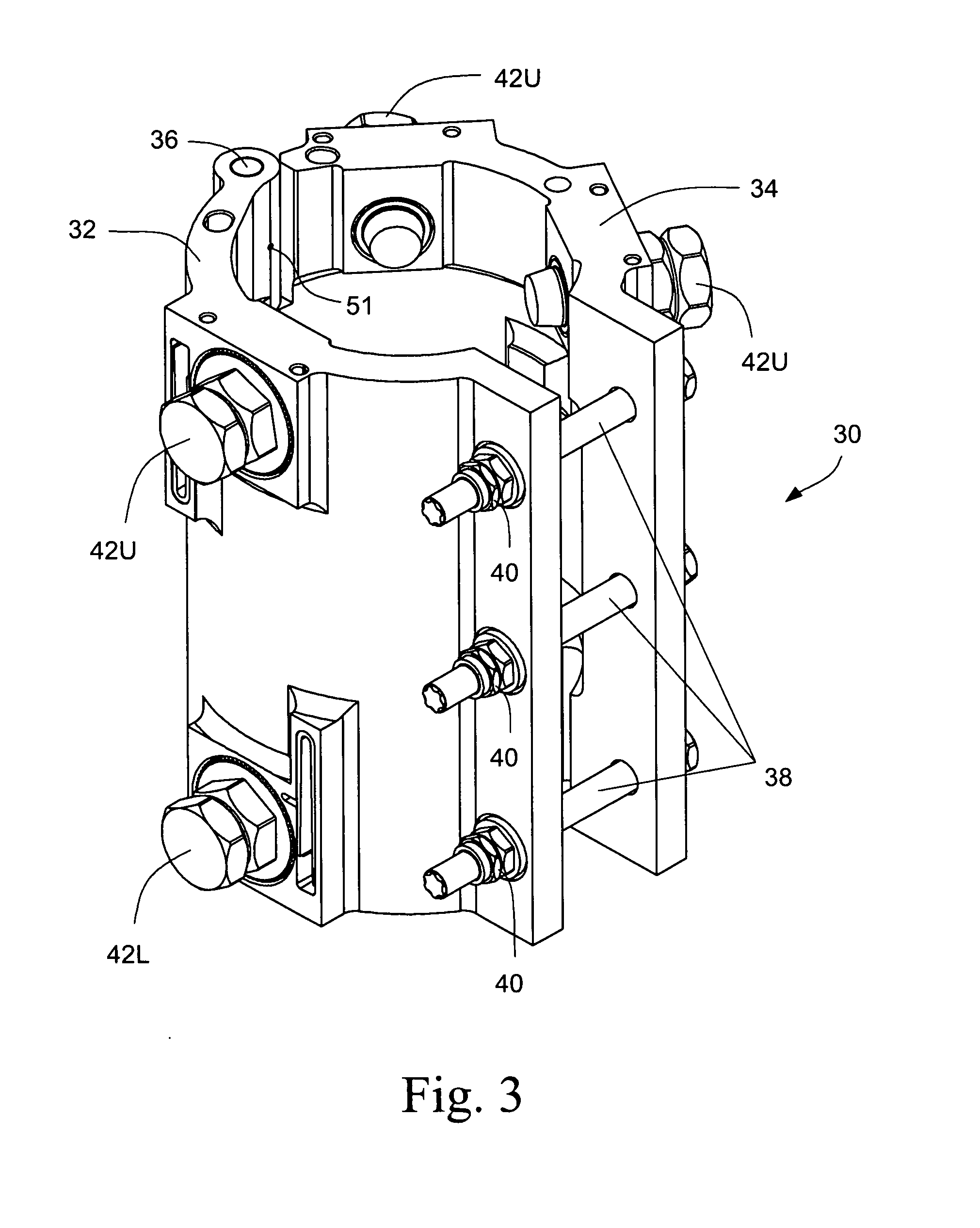
[0028]One embodiment of a slip joint clamp assembly 30 is shown in isometric representation in FIG. 3. The clamp assembly 30 includes a primary clamp housing 32 and a secondary clamp housing 34, which are rotationally joined together by a hinge assembly including a hinge pin 36 inserted through a plurality of hinge knuckles 46 attached to primary and secondary clamp housings 32 and 34. One embodiment of the hinge pin 36, which joins the primary and secondary clamp housings 32 and 34 together, is shown in FIG. 19.

[0029]The design of the primary and secondary clamp housings 32 and 34 are similar, as can be seen from FIGS. 10 through 13. The primary clamp housing 32 include...


PUM


Abstract

A slip joint clamp is disclosed which structurally replaces cracked welded joints in the core spray downcomer slip joint coupling, which is part of the lower portion of internal core spray piping internal to a reactor vessel of a Boiling Water Reactor plant. The internal piping delivers core spray cooling water to the reactor core region. The clamp assembly consists of a primary clamp housing and a secondary clamp housing, which are rotationally joined together by a hinge assembly including a hinge pin. The clamp assembly is installed at a desired elevation relative to the downcomer slip joint, and then secured to the downcomer piping by installing coupling bolts and associated coupling bolt keeper nuts that hold the primary and secondary clamp housings in a facing relationship to one another around the downcomer slip joint.

Description

[0001]The present invention relates to core spray piping systems in operating boiling water reactors (BWRs), and more particularly to a repair device for structurally replacing cracked welded joints in the core spray downcomer pipe slip joint coupling.BACKGROUND OF THE INVENTION[0002]Common to most operating BWR's, the core spray cooling water is delivered to the reactor core region by piping internal to the reactor vessel. The core spray piping systems in operating BWR's are of welded construction. The welds in the original core spray system piping are susceptible to Intergranular Stress Corrosion Cracking (IGSCC).[0003]The lower portion of BWR's internal core spray piping is commonly referred to as the “downcomer piping”. There are a total of four vertical downcomer pipes, which supply cooling water to sparger piping interior to the shroud 14. Two of these downcomer pipes 10 located on one side of the shroud 14 are shown in FIG. 1. Each of the downcomer pipes 10 consists of two se...

Claims


Application Information

Patent Timeline
Patent Type & Authority Applications(United States)
IPC IPC(8): F16L55/18
CPCF16L13/06F16L55/1705F16L55/172Y02E30/31G21C19/02G21C19/207G21C15/18Y02E30/30
Inventor JENSEN, GRANT CLARK
Owner GE HITACHI NUCLEAR ENERGY AMERICAS
Why Eureka
Try Eureka