Ring Motor

a ring motor and rotor technology, applied in the field of ring motors, can solve the problems of difficult assembly on site, and difficulty in positioning active magnetic means on the rotor, and achieve the effects of convenient assembly, convenient assembly, and simplified fitting of rotor poles

Inactive Publication Date: 2010-02-11
SIEMENS AG
View PDF16 Cites 17 Cited by
  • Summary
  • Abstract
  • Description
  • Claims
  • Application Information

AI Technical Summary

Benefits of technology

[0008]According to various embodiments, a ring motor can be created, which can be easily manufactured, transported and assembled in the plant without major assembly effort. In doing so, it must be possible to carry out all electrical te

Problems solved by technology

A disadvantage, particularly because of the comparatively large dimensions of these direct drives, is the assembly on site, as the components, such as stator or rotor, cannot be transported as a complete arrangement.
Accordingly, assembly on site i

Method used


Image

  • Ring Motor
  • Ring Motor
  • Ring Motor

Examples


Embodiment Construction

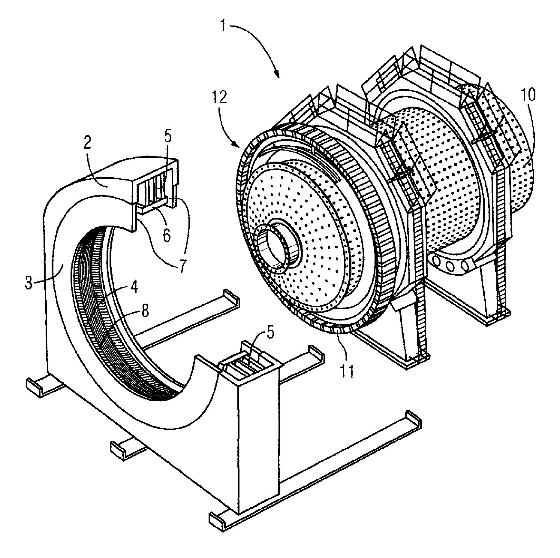
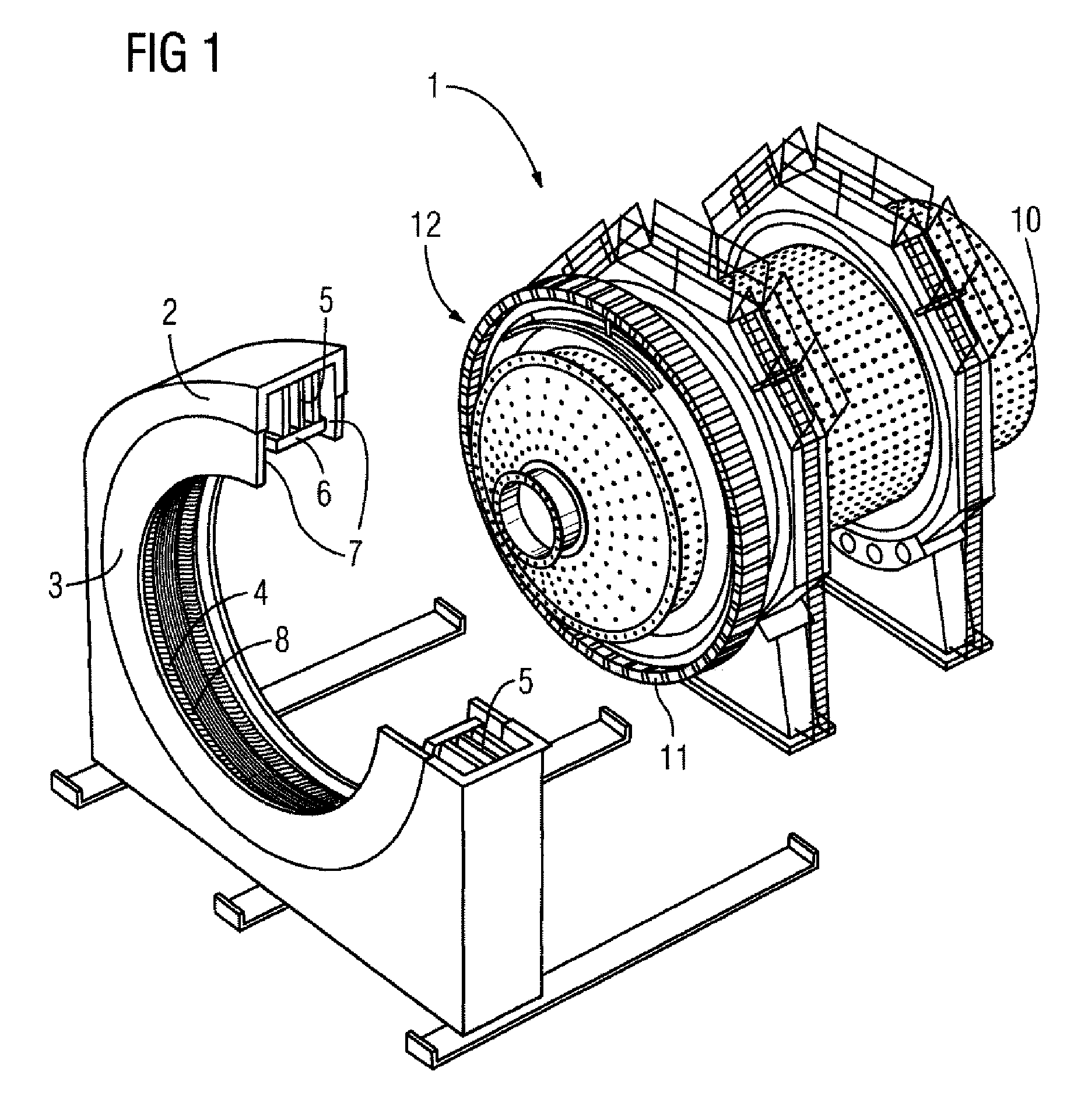
[0018]According to various embodiments, a ring motor as a direct drive, particularly for ore mills or rod mills, may comprise a stator and a rotor configured as a rotating mill body, wherein the stator has at least two different excitation systems, and the mill body has a toothed structure, which electromagnetically interacts with the excitation systems of the stator and thus brings about a rotation of the mill body.

[0019]As a result of the design of the ring motor according to various embodiments, the stator now has two different excitation systems which were previously distributed between stator and rotor. Consequently, this dispenses with the laborious handling and assembly with pre-magnetized poles on the mill body and / or also the magnetization of these rotor segments on site.

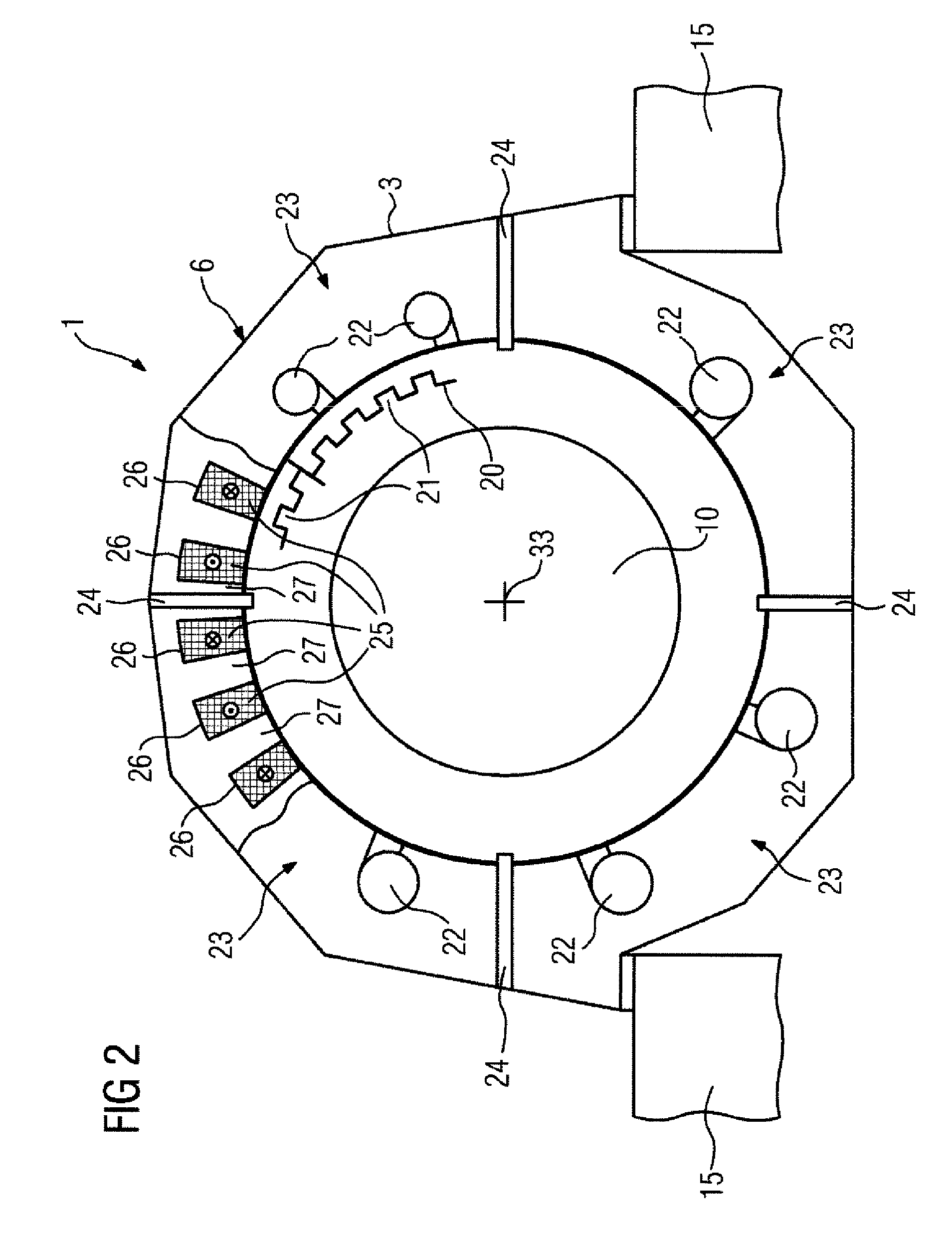
[0020]In a further preferred embodiment, the stator is provided with a winding system which is designed in the form of a tooth-coil system, wherein each tooth, or each second tooth of the stator viewed in t...


PUM


Abstract

A ring motor (1) as a direct drive, particularly for vertical mills or rod mills, has a stator (6) and a rotor (12) configured as a rotating milling body (10), wherein the stator (6) has at least two different excitation systems, and the milling body (10) has only a toothed structure, which electromagnetically interacts with the excitation systems of the stator (6) and thus brings about a rotation of the milling body (10).

Description

CROSS-REFERENCE TO RELATED APPLICATIONS[0001]This application is a U.S. National Stage Application of International Application No. PCT / EP2008 / 050447 filed Jan. 16, 2008, which designates the United States of America, and claims priority to German Application No. 10 2007 005 131.1 filed Feb. 1, 2007, the contents of which are hereby incorporated by reference in their entirety.TECHNICAL FIELD[0002]The invention relates to a ring motor as a direct drive, particularly for ore mills or rod mills, comprising a stator and a rotor configured as a rotating mill body.BACKGROUND[0003]For a long time, a direct drive of a horizontally arranged mill body has been provided in so-called mill drives, such as are used for milling cement or ores, in particular copper ores. For this purpose, the dynamo-electric drive motor is arranged concentrically with respect to the mill body, wherein the rotor and stator have comparatively large diameters in the region of greater than 5 m (U.S. Pat. No. 3,272,444)...

Claims


Application Information

Patent Timeline
IPC IPC(8): H02K21/38H02K7/14B02C17/24
CPCB02C17/24H02K21/44H02K7/14H02K1/16
Inventor HOSLE, MARKUS
Owner SIEMENS AG
Why Eureka
Try Eureka