
Dose composition suitable for low wattage ceramic metal halide lamp

a technology of ceramic metal halide and composition, which is applied in the manufacture of electric discharge tubes/lamps, gaseous cathodes, electrode systems, etc., can solve the problems of depletion of fill constituents, reactive properties of fused quartz, and certain properties at high operating temperatures

Inactive Publication Date: 2010-02-11
GENERAL ELECTRIC CO
View PDF10 Cites 7 Cited by
  • Summary
  • Abstract
  • Description
  • Claims
  • Application Information

AI Technical Summary

Benefits of technology

[0012]One advantage of at least one embodiment of the present disclosure is the provision of a lamp with improved performance and luminous efficiency.
[0013]Another advantage of at least one embodiment of the present disclosure resides in high color rendering index.

Problems solved by technology

Fused quartz, however, has certain disadvantages, which arise from its reactive properties at high operating temperatures.
For example, in a quartz lamp, at temperatures greater than about 950-1000° C., the halide filling reacts with the glass to produce silicates and silicon halide, which results in depletion of the fill constituents.
Elevated temperatures also cause sodium to permeate through the quartz wall, which causes depletion of the fill.
Both depletions cause color shift over time, which reduces the useful lifetime of the lamp.
These lamps are limited in performance by the maximum wall temperature achievable in the quartz arctube.
One problem with such lamps is that the light output deviates from that of “white” light.
The properties of high intensity discharge lamps operated at high temperatures tend to suffer.
Ceramics operated at high temperature degrade in their mechanical strength, and consequently the lamps may not withstand the stresses on the ceramic that are present during lamp operation.
This leads to premature lamp failure or poor reliability.

Method used


Image

  • Dose composition suitable for low wattage ceramic metal halide lamp
  • Dose composition suitable for low wattage ceramic metal halide lamp
  • Dose composition suitable for low wattage ceramic metal halide lamp

Examples


example 1

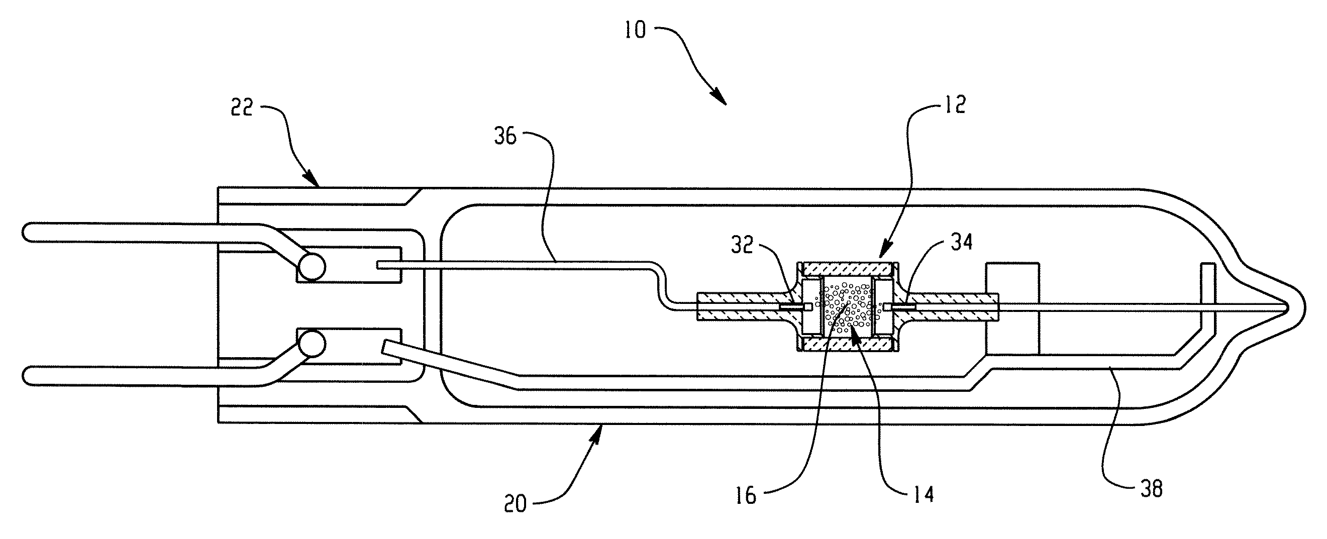
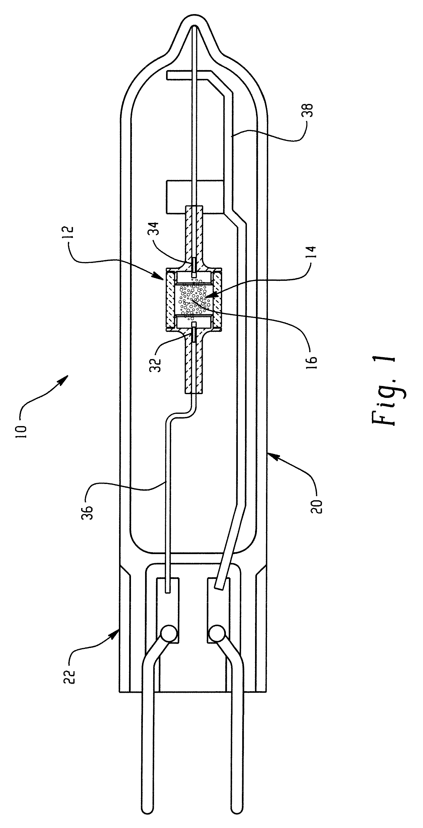
[0074]A 39W Ceramic Metal Halide Single-Ended lamp according to the embodiment shown in FIG. 1, was formed with an arc gap of 4.65 mm, a barrel length L of 7.3 mm, a dose weight of 8.8 mg, or 47.2 mg / cc and mole fractions of: NaI: 0.562, TlI: 0.022, CaI2: 0.305, and LaI3: 0.111 (totaling 1.0) in a fill containing mercury (5.7 mg) and argon gas at a fill pressure of 120 Torr. Table 2 illustrates additional properties of the lamp.

TABLE 2Test CellSample AWall Thickness Tb (mm)0.6Plug Thickness Tp (mm)0.6Plug Depth d (mm)1.8Inner Diameter D (mm)5.7Tip-To-Plug TTP (mm)1.33Wall Loading WL (W / cm2)21.5Lumens (LPW) @ 100 hours90CCT (degrees K)3012CRI (Ra)86dCCY−0.004Maximum Wall Temperature (degrees K)1380

example 2

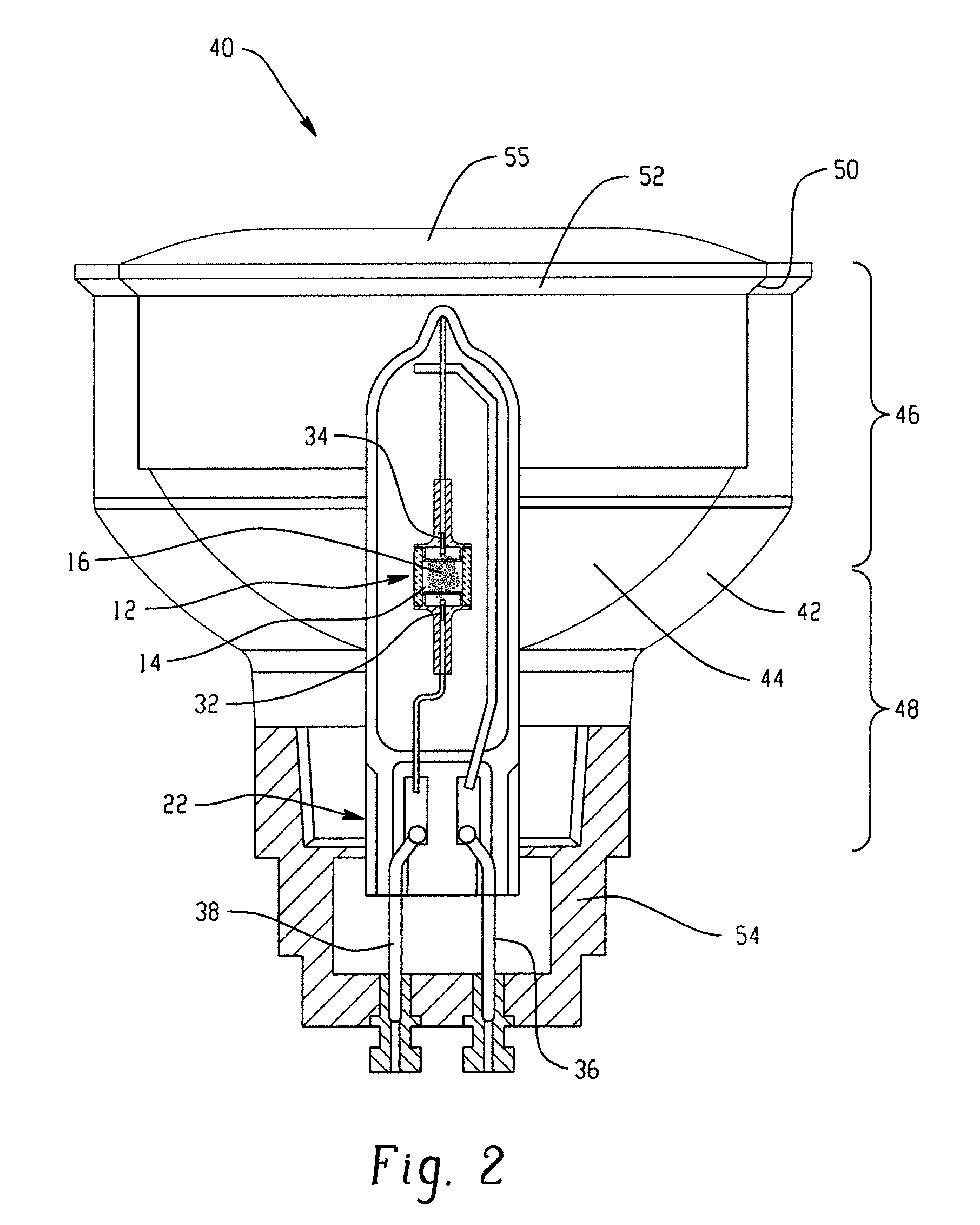
[0075]A 39W Ceramic Metal Halide lamp, housed in a lamp housing having a reflective interior surface as illustrated in FIG. 2, was formed with an arc gap of 4.65 mm, a barrel length L of 7.3 mm, a dose weight of 6.4 mg, or 34.4 mg / cc and mole fractions of: NaI: 0.574, TlI: 0.021, CaI2: 0.297, and LaI3: 0.108 (totaling 1.0) in a fill containing mercury (5.5 mg) and argon gas at a fill pressure of 120 Torr. Table 3 illustrates a lower LPW for a CMH lamp housed in a lamp having a reflecture compared to a lamp without a housing. Table 3 illustrates additional properties of the lamp.

TABLE 3Test CellSample BWall Thickness Tb (mm)0.6Plug Thickness Tp (mm)0.6Plug Depth d (mm)1.8Inner Diameter D (mm)5.7Tip-To-Plug TTP (mm)1.33Wall Loading WL (W / cm2)21.5Lumens (LPW) @ 100 hours63CCT (degrees K)3050CRI (Ra)89dCCY−0.002Maximum Wall Temperature (degrees K)1450

As can be seen from Table 3, there was a loss in lumen output resulting from the use of a lamp housing, although, other properties were su...

example 3

[0076]A 39W Ceramic Metal Halide Single-Ended lamp according to the embodiment shown in FIG. 1, was formed with an arc gap of 4.65 mm, a barrel length L of 7.6 mm, a dose weight of 8.0 mg, or 41.25 mg / cc and mole fractions of: NaI: 0.677, TlI: 0.047, CaI2: 0.201, and LaI3: 0.074 (totaling 1.0) in a fill containing mercury (5.3 mg) and argon gas at a fill pressure of 120 Torr. Table 4 illustrates additional properties of the lamp.

TABLE 4Test CellSample DWall Thickness Tb (mm)0.6Plug Thickness Tp (mm)0.6Plug Depth d (mm)1.8Inner Diameter D (mm)5.7Tip-To-Plug TTP (mm)1.48Wall Loading WL (W / cm2)20.8

[0077]In another study, targets for photometric values were established as follows:

La Mole Fraction0.08Lumens3590CRI87CCT2900dCCy0.001

[0078]In one experiment, the mole fraction of lanthanum halide in lamps otherwise similar to those of Example 1 was varied at 3 levels (0.05, 0.08, and 0.11 mol fraction). However, the results indicated that the lamps with the 0.08 mol fraction most closely mat...


PUM


Abstract

A lamp includes a discharge vessel with electrodes extending into the discharge vessel and an ionizable fill sealed within the vessel. The fill includes a buffer gas, optionally mercury, and a halide component comprising a sodium halide, a lanthanum halide, a thallium halide, and a calcium halide. The lanthanum halide is present in the halide component at a mol fraction of at least 0.03.

Description

[0001]This application claims the priority, as a continuation-in part, of U.S. Application Ser. No. 12 / 032,715, filed Feb. 18, 2008, entitled “Dose Composition Suitable For Hollow Plug Ceramic Metal Halide Lamp,” the disclosure of which is incorporated herein by reference in its entirety.BACKGROUND OF THE DISCLOSURE[0002]The present invention relates generally to ceramic arc discharge lamps and more particularly to a discharge lamp with an end zone having reduced wall thickness and a dose comprising sodium, thallium, calcium, and lanthanum, generally in the form of their halides, which is suitable for lamps having a wattage in the range of 15-100 watts.[0003]Discharge lamps produce light by ionizing a fill material, such as a mixture of metal halide and mercury in an inert gas, such as argon, with an arc passing between two electrodes. The electrodes and the fill material are sealed within a translucent or transparent discharge chamber, which maintains the pressure of the energized ...

Claims


Application Information

Patent Timeline
Patent Type & Authority Applications(United States)
IPC IPC(8): H01J61/20H05B41/00H01J9/00
CPCH01J9/247H01J61/125H01J61/827H01J61/30H01J61/34H01J61/26
Inventor RAMAIAH, RAGHU
Owner GENERAL ELECTRIC CO
Learn More