
Lamp with IR suppressing composite

a technology of composite lamps and incandescent lamps, which is applied in the manufacture of discharge tubes/lamps, discharge tubes main electrodes, electric discharge tubes/lamps, etc., can solve the problems of increased probability of coil breakage, failure of lamps, and high defect rate that cannot be tolerated, so as to improve thermal stress, improve performance and luminous efficiency, and reduce brittleness

Inactive Publication Date: 2011-06-21
GENERAL ELECTRIC CO
View PDF14 Cites 6 Cited by
  • Summary
  • Abstract
  • Description
  • Claims
  • Application Information

AI Technical Summary

Benefits of technology

The solution provides improved thermal stability, reduced brittleness, and increased luminous efficiency, leading to a lamp with enhanced performance and longer lifespan by minimizing thermal expansion and interface diffusion.

Problems solved by technology

This partial re-crystallization significantly increases the probability that the coil will break.
This leads to the failure of the lamp in a short time.
Since for these lamps, the allowed defect rate is critical for marketability, a high defect rate cannot be tolerated.

Method used


Image

  • Lamp with IR suppressing composite
  • Lamp with IR suppressing composite
  • Lamp with IR suppressing composite

Examples


example

Example 1

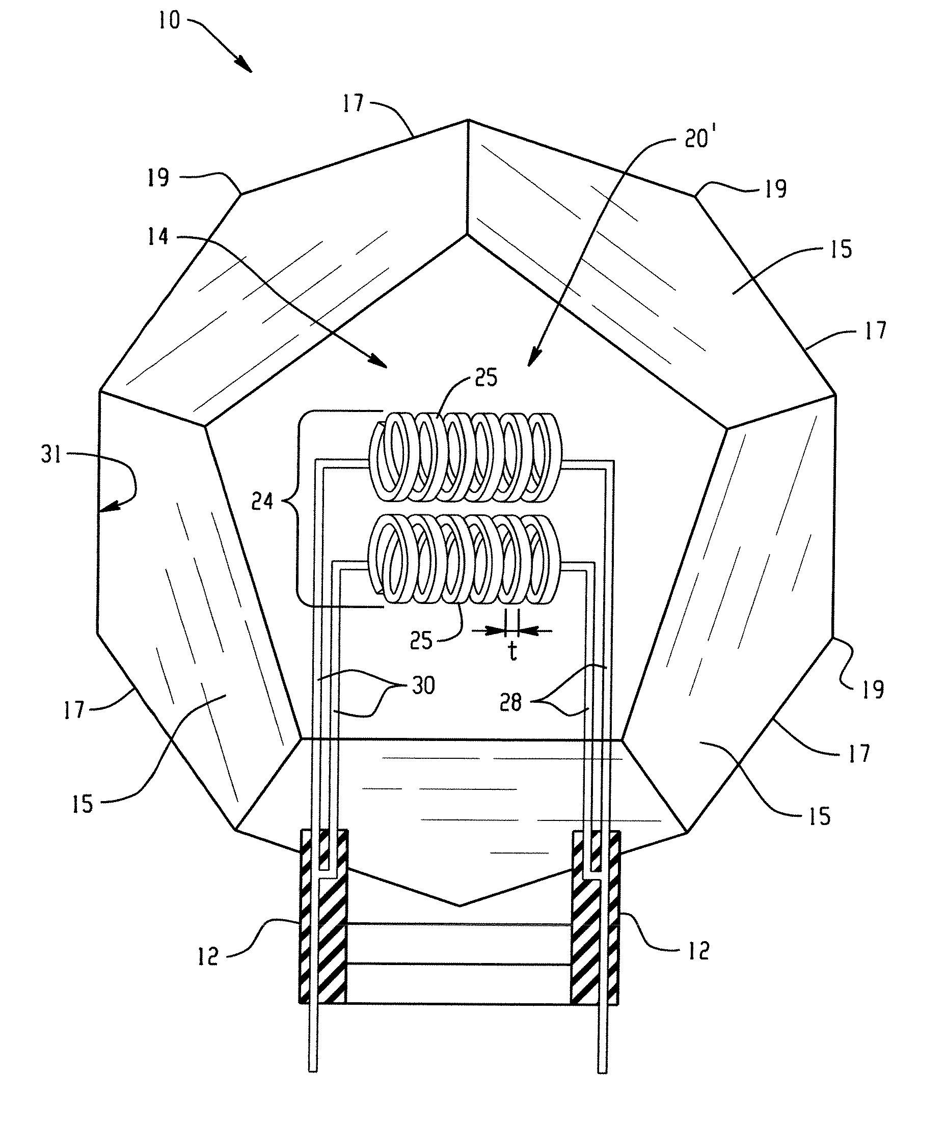
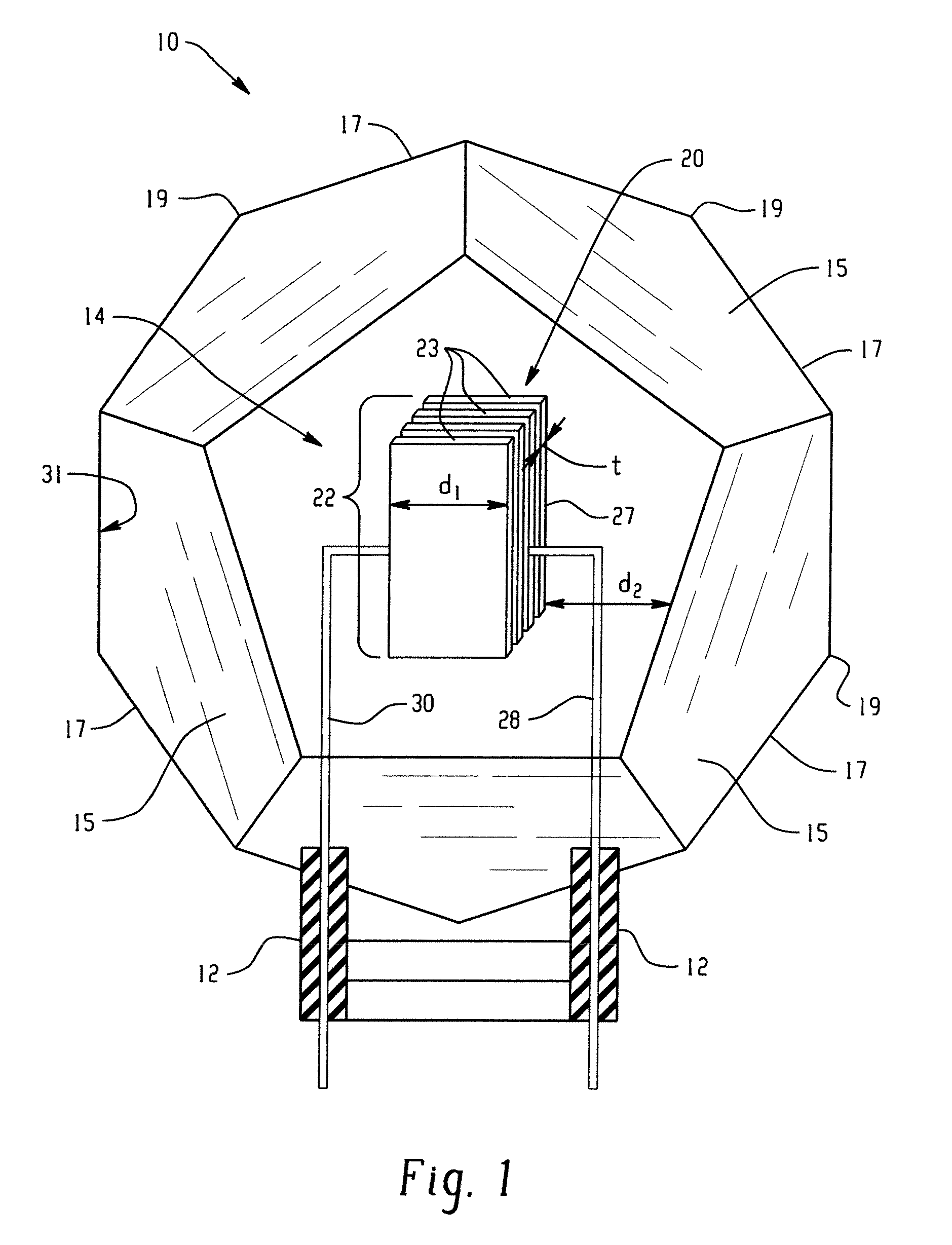
[0060]Single coil tungsten filament lamps according to the exemplary embodiment were formed with a filament diameter of about 80 μm. The tungsten substrate was doped with tantalum and rhenium at the surface less than about 5 nm. The filament was coated with molybdenum diboride doped with about 5 wt % titanium, tantalum carbide, and tantalum carbonitride with thicknesses of 200 nm, less 400 nm and 500 nm respectively. The coating layer had a total thickness of less than about 1.2 μm. The surface was made denser, less than about 5 wt % porosity, with a pulse hydrogen burner for 30 minutes under an argon flow. As illustrated in FIG. 7, in one embodiment the coating layer may be configured for the color temperature of the lamp to increase with nitrogen and decrease with boron from a baseline correlated color temperature of about 3000K. For example, a nitrogen content of about 20 wt % but less than about 25 wt % may exhibit a CCT, e.g. of about 3400K, e.g., less than about 3600K...


PUM

PropertyMeasurementUnit
thicknessaaaaaaaaaa
thicknessaaaaaaaaaa
thicknessaaaaaaaaaa

Abstract

A lamp includes a filament for emitting light. The filament includes an emissive substrate which emits radiation when an electric current is applied. The substrate includes a doped surface and a coating layer supported on the doped surface. The coating layer includes at least one of a carbonitride and a boride.

Description

BACKGROUND OF THE DISCLOSURE[0001]The exemplary embodiment relates to increasing efficiency in an incandescent lamp. It finds particular application with regard to lamps comprising a tungsten or carbon filament, such as a rhenium and carbonitride containing filament, for reducing thermal stress and brittleness while increasing the efficiency of a lamp, and will be described with particular reference thereto.[0002]Tungsten or carbon filaments for incandescent lamps are well known in the art. In most applications, the filaments are made of a wire which is wound into a coil. Coil dimensions determine not only the achievable light output of the lamp, but also the optical projector system of the lamp.[0003]During filament production, the coiled filaments are annealed (heat treated to preserve the shape of the filament). This annealing serves to enable the assembly of the filaments on an automated mounting machine without breaking. During the annealing of the coils, that part of the coils...

Claims


Application Information

Patent Timeline
Patent Type & Authority Patents(United States)
IPC IPC(8): H01J1/14
CPCH01K1/10H01K1/28H01K1/14
Inventor AURONGZEB, DEEDEROLWERT, RONALD JAMES
Owner GENERAL ELECTRIC CO
Learn More