Flat transmission wire and fabricating methods thereof

a transmission wire and flat technology, applied in the field of flat transmission wire, can solve the problems of inconvenient installation of conventional round cable wires, poor appearance, negative influence on the environment, etc., and achieve the effect of reducing crosstalk and transmission loss, simple installation, and good appearan

Inactive Publication Date: 2010-02-11
NANO CHEM TECH INC
View PDF17 Cites 8 Cited by
  • Summary
  • Abstract
  • Description
  • Claims
  • Application Information

AI Technical Summary

Benefits of technology

[0009]In view of the above problems, an object of the present invention is to provide a flat transmission wire that is simple to install, has good appearance and can effectively minimize crosstalk and transmission loss.

Problems solved by technology

Conventional round cable wires are inconvenient to install, have poor appearance because round lines tend to be exposed to the outside, have a heavy unit weight, and have a negative influence on the environment due to carbon dioxide being emitted during fabrication processes.
However, the non-uniform flat transmission wire suffers from a noise loss resulting from non-uniform and discontinuous intervals between the transmission lines under actual conditions of use.
This noise loss shortens the transmission distance of the transmission lines and increases the loss of transmission signal, which limit the signal transmission of the flat transmission wire.
This attachment or deposition makes it difficult to form a fine pattern of the transmission lines.
Further, the conventional methods involve complicated steps, incur high costs, and cause environmental problems during deposition.
In the event that only the insulator film is used in the transmission wire, crosstalk or loss of transmission signal may be caused because no electromagnetic shielding effect is expected.
Meanwhile, the use of the aluminum foil / fully deposited film as electromagnetic shielding causes difficulty in controlling the impedance of the transmission wire, despite the excellent electromagnetic shielding effect, and is disadvantageous in terms of thickness and price.

Method used


Image

  • Flat transmission wire and fabricating methods thereof
  • Flat transmission wire and fabricating methods thereof
  • Flat transmission wire and fabricating methods thereof

Examples


example 1

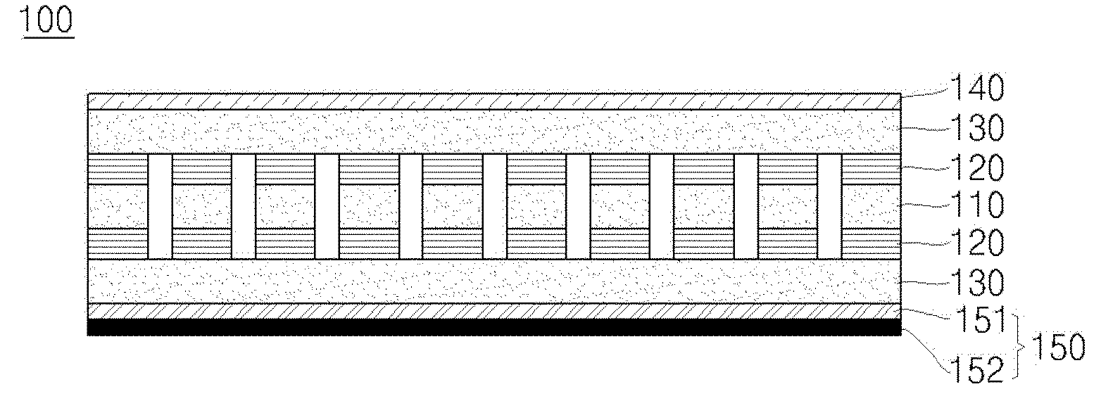
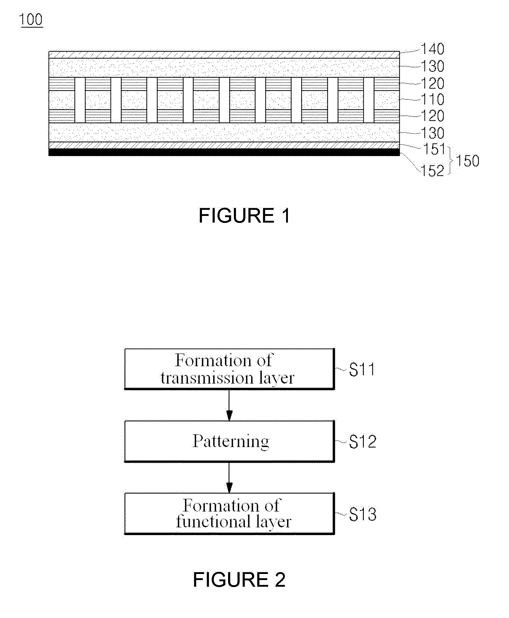
[0087]1-1. A heat-curable acrylic pressure-sensitive adhesive having an adhesive strength of 60 gf / 25 mm was coated to a thickness of 20 μm on both surfaces of a polyethylene film (thickness=0.05 mm, width=50 mm) by gravure coating, and dried at 100° C. for 10 min to form pressure-sensitive adhesive layers.

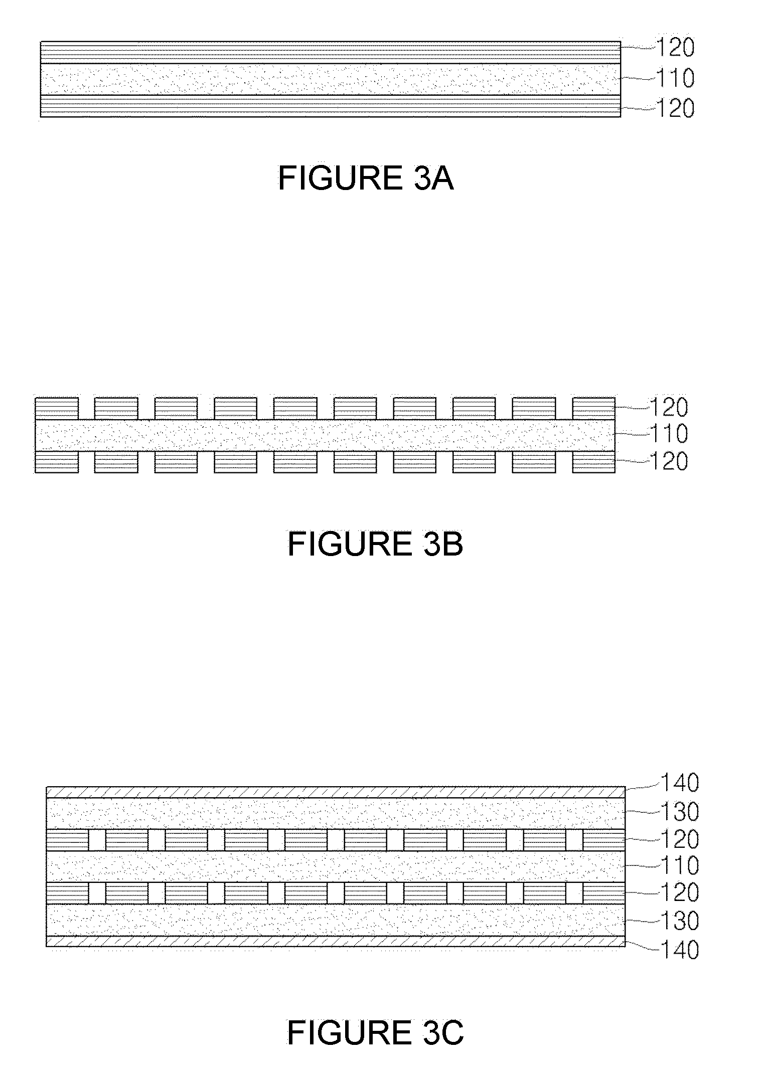
[0088]1-2. Copper was adhered to both surfaces of the polyethylene film through the pressure-sensitive adhesive layers to form transmission layers.

[0089]1-3. Each of the transmission layers was slit to form four linear transmission lines. The transmission lines had a width of 5 mm and were spaced apart from each other at intervals of 5 mm.

[0090]1-4. An acrylic adhesive having an adhesive strength of 60 gf / 25 mm was coated to a thickness of 20 μm on one surface of a polyethylene film (thickness=0.05 mm, width=20 mm) by gravure coating, and dried at 100° C. for 30 min to form an adhesive layer. The polyethylene film was adhered to one of the transmission layers including the transmi...

example 2

[0091]2-1. An acrylic adhesive having an adhesive strength of 1,000 gf / 25 mm was coated to a thickness of 20 μm on both surfaces of an insulating film (thickness=0.05 mm, width=50 mm) by gravure coating, and dried at 100° C. for 30 min to form adhesive layers.

[0092]2-2. Two transmission layers having transmission lines, which were produced in the same manner as in 1-1 through 1-3, were adhered to both surfaces of the insulating film through the adhesive layers.

[0093]2-3. A polyethylene film having an adhesive layer formed on one surface thereof, which was produced in the same manner as in 1-4, was adhered to one surface of each of the transmission layers to fabricate a flat transmission wire.

example 3

[0094]3-1. A heat-curable acrylic adhesive having an adhesive strength of 1,000 gf / 25 mm was coated to a thickness of 20 μm on both surfaces of a polyethylene film (thickness=0.05 mm, width=50 mm) by gravure coating, and dried at 100° C. for 10 min to form adhesive layers. Copper was adhered to one surface of the polyethylene film through one of the adhesive layers to form a transmission layer.

[0095]3-2. The polyethylene film having the transmission layer formed on one surface thereof was adhered to one surface of one of two transmission layers of a polyethylene film, which was produced in the same manner as in 1-1 and 1-2.

[0096]3-3. The polypropylene film and the transmission layers were converted in the same manner as in 1-3 to form five transmission lines.

[0097]3-4. A polyethylene film was adhered to one surface of each of the transmission layers including the transmission lines to fabricate a flat transmission wire.


PUM

PropertyMeasurementUnit
adhesive strengthaaaaaaaaaa
temperatureaaaaaaaaaa
thicknessaaaaaaaaaa

Abstract

A flat transmission wire is provided which includes a first insulating or dielectric film, a transmission layer formed on at least one surface of the first insulating or dielectric film so as to transmit electrical signals therethrough, a second insulating or dielectric film formed on one surface of the transmission layer, and a functional layer formed on one surface of the second insulating or dielectric film. Further provided are methods for fabricating flat transmission wires which enable the formation of uniform and fine transmission line patterns, and are environmental friendly, as compared to deposition-based methods.

Description

CROSS-REFERENCE TO RELATED APPLICATION[0001]This application claims priority to and the benefit of Korean Patent Applications No. 10-2008-0077963, filed on Aug. 8, 2008, No, 10-2009-0014085, filed on Feb. 19, 2009, and No. 10-2009-0026407, filed on Mar. 27, 2009, the entire content of which is incorporated herein by reference.BACKGROUND OF THE INVENTION[0002]1. Field of the Invention[0003]The present invention relates to a flat transmission wire and methods for fabricating the same. More specifically, the present invention relates to a flat transmission wire that is light in weight, simple to install, which has a good appearance and can effectively minimize crosstalk and transmission loss in the wire, as well as methods for fabricating flat transmission wires in a simple and environmentally friendly manner at low cost.[0004]2. Description of the Related Art[0005]A transmission wire is a signal transmission path having an electrical length. Conventional round cable wires are inconven...

Claims


Application Information

Patent Timeline
Patent Type & Authority Applications(United States)
IPC IPC(8): H01P5/12H05K3/10
CPCB82Y10/00Y10T29/49155H05K1/0224H05K1/0259H05K1/0393H05K1/167H05K2201/026H05K2201/0326H05K2201/0329H05K2201/0715H05K2201/09236H05K2201/09672H05K2201/09681H05K2203/121H05K1/0218
Inventor BAIK, WOON PHILJANG, KWAN SIK
Owner NANO CHEM TECH INC
Why Eureka
Try Eureka