Position detecting device and position detecting method

a position detection and position detection technology, applied in the field of improving scanning speed, can solve problems such as problems such as integration processing and a/d conversion processing, and achieve the effect of simple circuit configuration

Active Publication Date: 2010-02-11
WACOM CO LTD
View PDF28 Cites 27 Cited by
  • Summary
  • Abstract
  • Description
  • Claims
  • Application Information

AI Technical Summary

Benefits of technology

[0049]According to various embodiments of the present invention, it is possible to provide an electrostatic capacity type position detecting device and a position detecting method capable of performing high speed scanning with a relatively simple circuit configuration.

Problems solved by technology

On position detecting devices that are relatively larger in size, problems will arise with the integration processing and the A / D conversion processing for each intersection.

Method used


Image

  • Position detecting device and position detecting method
  • Position detecting device and position detecting method
  • Position detecting device and position detecting method

Examples


Embodiment Construction

)

[0059]An embodiment of the present invention will be described below with reference to FIGS. 1 to 7.

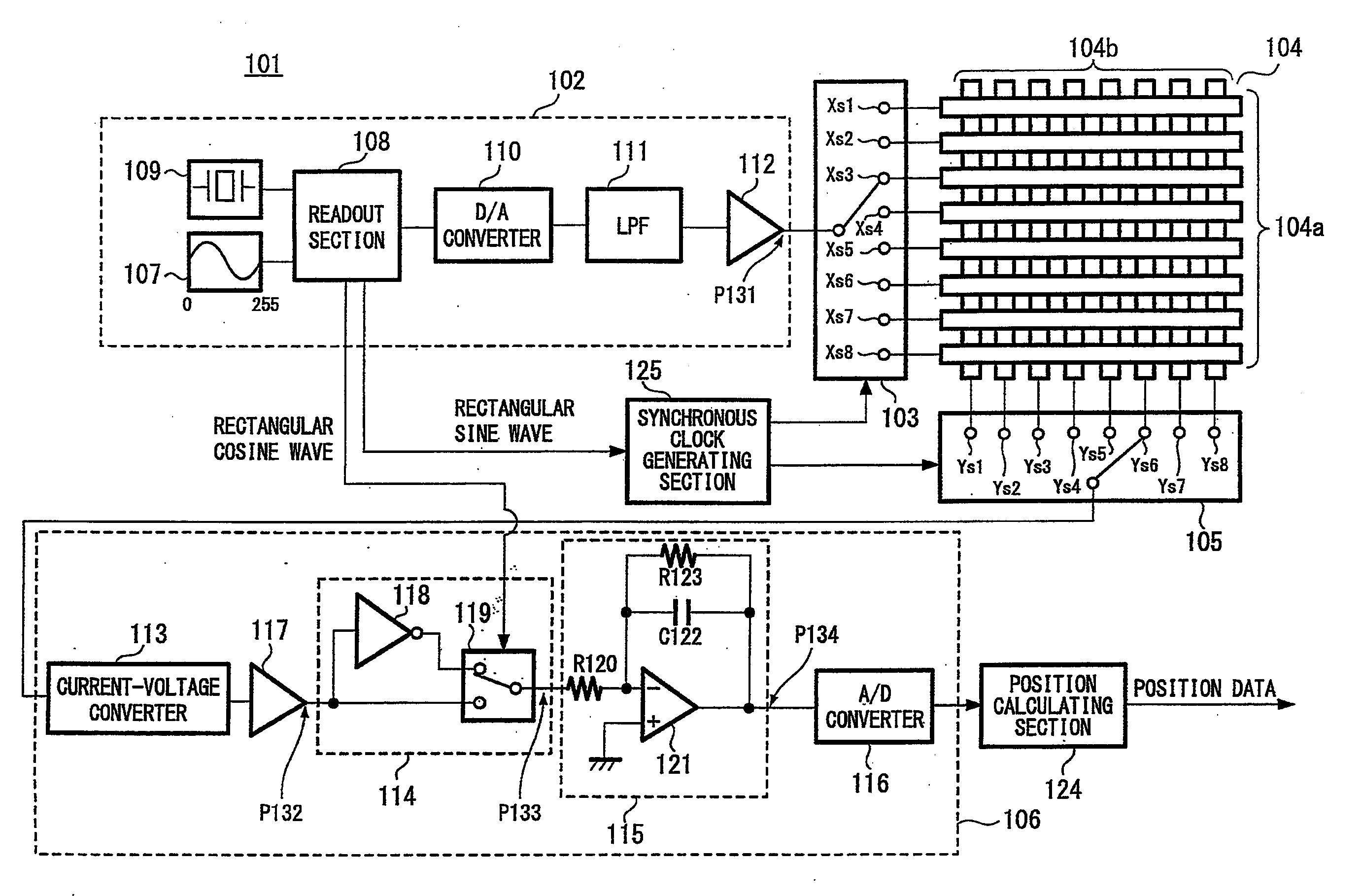
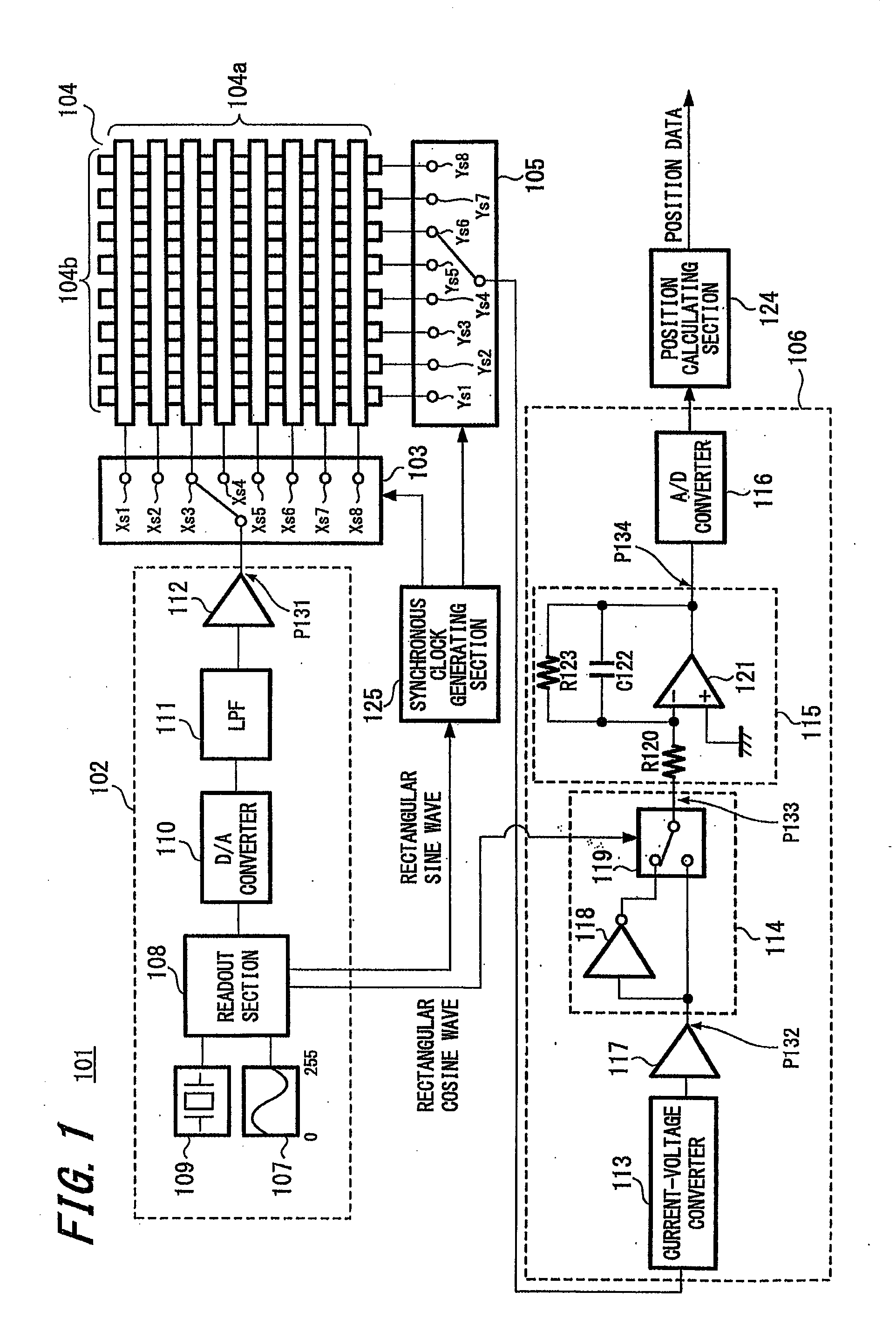
[0060]A configuration of a position detecting device 101 according to the embodiment will be described with reference to FIG. 1. The position detecting device 101 includes a driving section 102, an X-axis electrode side change-over switch 103, matrix electrodes 104, a Y-axis electrode side change-over switch 105, a receiving section 106, and a position calculating section 124.

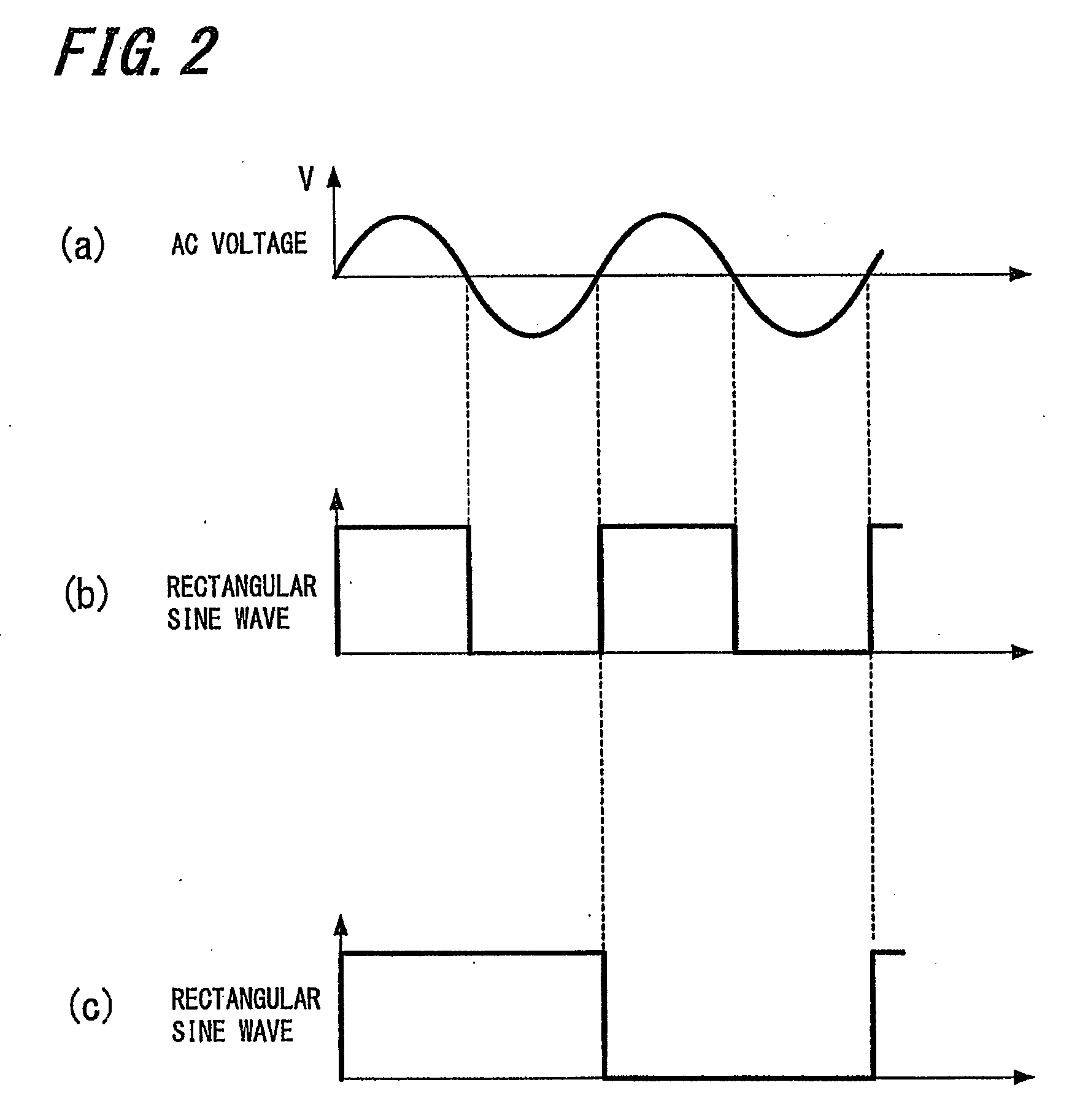
[0061]The driving section 102 generates an AC (Alternating Current) signal, including a signal with waveform (e.g., sine waveform) or a signal with pulse waveform, each having a frequency of 200 kHz, which is the frequency most easily absorbed by a human body. The AC voltage generated by the driving section 102 is applied to the matrix electrodes 104.

[0062]The matrix electrodes 104 are formed by a plurality of elongated conductive electrodes arranged longitudinally and latitudinally. Specifically, the matrix ele...


PUM


Abstract

A position detecting device includes: X-axis electrodes formed by a plurality of conductors that are arranged substantially parallel to each other; Y-axis electrodes formed by a plurality of conductors that are arranged substantially parallel to each other and that extend perpendicularly to the X-axis electrodes; a driving section for supplying an AC signal to the X-axis electrodes; a synchronous clock generating section for generating a synchronous clock at the time when the AC signal passes through zero-cross points; a first change-over switch for selectively supplying the AC signal outputted from the driving section to a predetermined electrode among the X-axis electrodes in response to the synchronous clock; a second change-over switch for selecting a predetermined electrode among the Y-axis electrodes in response to the synchronous clock; a synchronous detector for synchronous-detecting a signal outputted by the Y-axis electrodes through the second change-over switch based on the synchronous clock, and outputting the detected signal; and a position calculating section for calculating a position indicated by an indicator based on the signal outputted from the synchronous detector, the position corresponding to one or more intersections of the X-axis electrodes and Y-axis electrodes.

Description

CROSS REFERENCES TO RELATED APPLICATIONS[0001]The present application claims priority under 35 U.S.C. § 119 to Japanese Patent Application No. JP 2008-031857 filed in the Japanese Patent Office on Feb. 13, 2008, the entire contents of which are incorporated herein by reference.BACKGROUND OF THE INVENTION[0002]1. Field of the Invention[0003]The present invention relates to improving scanning speed of, for example, an electrostatic capacity type position detecting device.[0004]2. Description of the Prior Art[0005]There are various kinds of input devices for providing position information to a computer. One such device is a touch panel capable of detecting a position on a flat detection surface where a finger or a dedicated stylus pen touches. The touch panel will output an instruction corresponding to the detected position to the computer as input information. The touch panel is widely used in PDAs (Personal Digital Assistants), ATMs (Automated Teller Machines), railway ticket-vending...

Claims


Application Information

Patent Timeline
Patent Type & Authority Applications(United States)
IPC IPC(8): G06F3/041
CPCG06F3/044G06F3/041G06F3/0446G06F3/0416
Inventor MATSUBARA, MASAKI
Owner WACOM CO LTD
Why Eureka
Try Eureka