
System and Method for Iterative Interactive Ray Tracing in a Multiprocessor Environment

Inactive Publication Date: 2010-02-11
IBM CORP
View PDF15 Cites 31 Cited by
  • Summary
  • Abstract
  • Description
  • Claims
  • Application Information

AI Technical Summary

Benefits of technology

[0014]The following summary is provided to facilitate an understanding of some of the innovative features unique to the embodiments disclosed and is not intended to be a full descr

Problems solved by technology

Because global illumination techniques are frequently resource-intensive, some typical graphics systems use ambient occlusion to simulate global illumination.
Ambient occlusion and ray tracing's secondary rays add detail not available in ray casting, which results in more photorealistic images.
However, the additional rays also require additional computation and storage resources.
Such additional computation and storage requirements have often made interactive ray tracing impractical or impossible.
But ray tracing's secondary rays, and ambient occlusion rays, for example, typically do not share a common origin, and do not have a high degree of directional coherence.
As such, processing secondary rays, even with acceleration structures, is more complicated and computationally intensive than processing typical primary or shadow rays.
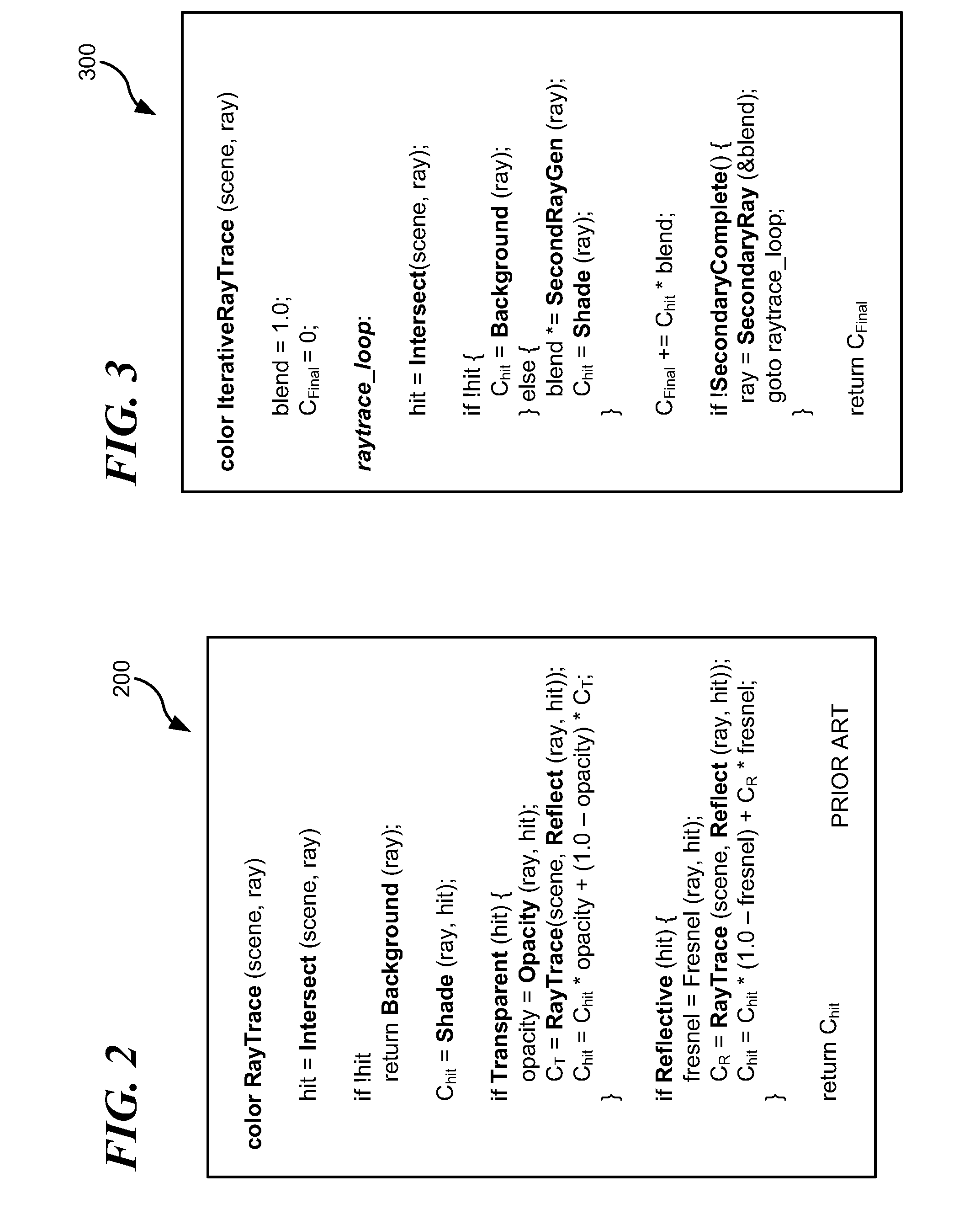
This recursion presents problems for multi-core processors such as the Cell™, Broadband Engine™, and certain special processing units, such as graphical processing units (GPUs), for example.
Specifically, certain such processors restrict local memory, which limits the space available for stack-based function invocation, making performance-prohibitive the complex recursion required in typical algorithms.
Nor does single-ray processing benefit from other latency solutions such as pipelining, for example.
As such, conventional Whitted-style ray tracing is often many times slower than simple ray casting, to the point where conventional ray tracing techniques cannot practically be performed interactively or otherwise in real-time.

Method used


Image

  • System and Method for Iterative Interactive Ray Tracing in a Multiprocessor Environment
  • System and Method for Iterative Interactive Ray Tracing in a Multiprocessor Environment
  • System and Method for Iterative Interactive Ray Tracing in a Multiprocessor Environment

Examples


Embodiment Construction

[0032]The particular values and configurations discussed in these non-limiting examples can be varied and are cited merely to illustrate at least one embodiment and are not intended to limit the scope of the invention.

[0033]In the following discussion, numerous specific details are set forth to provide a thorough understanding of the present invention. Those skilled in the art will appreciate that the present invention may be practiced without such specific details. In other instances, well-known elements have been illustrated in schematic or block diagram form in order not to obscure the present invention in unnecessary detail. Additionally, for the most part, details concerning network communications, electro-magnetic signaling techniques, user interface or input / output techniques, and the like, have been omitted inasmuch as such details are not considered necessary to obtain a complete understanding of the present invention, and are considered to be within the understanding of pe...


PUM


Abstract

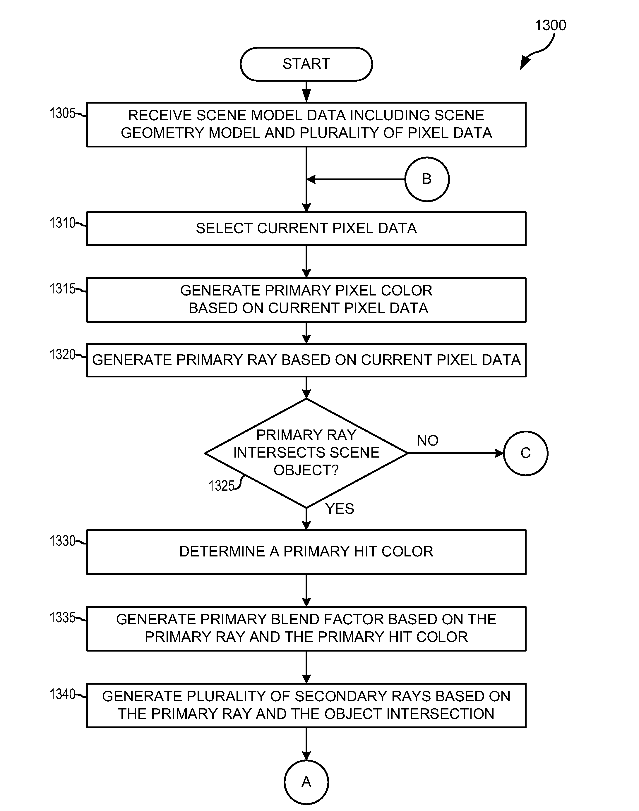
A method comprises receiving scene model data including a scene geometry model and a plurality of pixel data describing objects arranged in a scene. The method generates a primary ray based on a selected first pixel data. In the event the primary ray intersects an object in the scene, the method determines primary hit color data and generates a plurality of secondary rays. The method groups the secondary packets and arranges the packets in a queue based on the octant of each direction vector in the secondary ray packet. The method generates secondary color data based on the secondary ray packets in the queue and generates a pixel color based on the primary hit color data, and the secondary color data. The method generates an image based on the pixel color for the pixel data.

Description

TECHNICAL FIELD[0001]The present invention relates generally to the field of computer graphics and photorealistic image generation and, more particularly, to a system and method for improved iterative interactive ray tracing in a multiprocessor environment.BACKGROUND OF THE INVENTION[0002]Modern computer graphics systems and methods include a variety of techniques designed to render high-quality images for use in a wide variety of applications, including video games, flight and other simulation, motion pictures, and many other applications. For example, for animation studios, ray tracing and global illumination techniques now play an integral role in motion picture production and special effects.[0003]Many techniques focus on tracing the path an imaginary ray of light travels as it moves from a light source though a scene. In “ray casting,” for each pixel in a scene, a graphics system traces an imaginary ray from a selected observation point into the scene, to a selected light sourc...

Claims


Application Information

Patent Timeline
IPC IPC(8): G09G5/02
CPCG06T15/06G06T2210/52G06T15/50
Inventor NUTTER, MARK R.FOSSUM, GORDON C.MADRUGA, JOAQUINMINOR, BARRY L.
Owner IBM CORP
Learn More