
Apparatus for cooling heat generating spot of electronic device, cooling method therefore, and liquid crystal projector apparatus

Active Publication Date: 2010-02-11
SHARP NEC DISPLAY SOLUTIONS LTD
View PDF7 Cites 10 Cited by
  • Summary
  • Abstract
  • Description
  • Claims
  • Application Information

AI Technical Summary

Benefits of technology

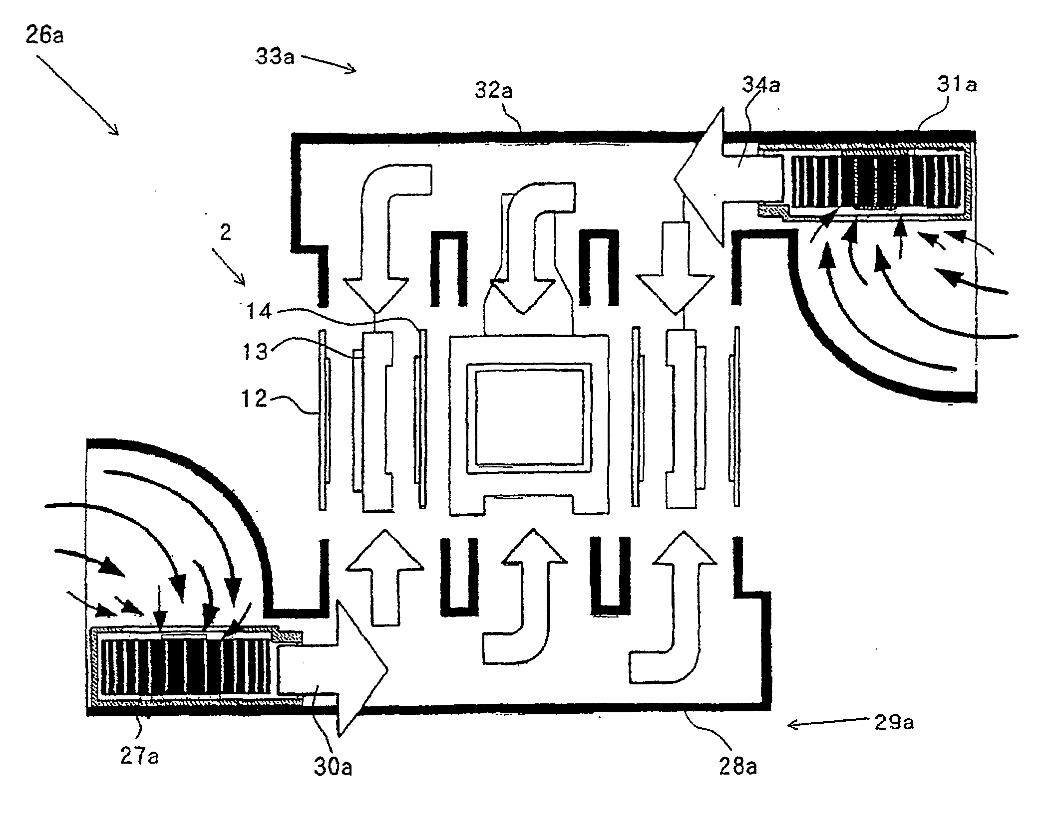
[0039]In the apparatus for cooling a heat generating spot of an electronic device in the present invention, for example, when applied to a cooling mechanism for a liquid crystal image display, a pair of air cooling means disposed in opposition in the vertical direction across a liquid crystal unit interposed therebetween, are used to cause air streams to collide in an opposing state in a space between a liquid crystal panel and a polarizing plate, thereby generating an impinging jet flow perpendicular to each heat generating plane of the liquid crystal panel and polarizing plate. In this way, the heat transfer coefficient can be significantly improved to promote the heat transfer, as compared with the cooling of a liquid crystal unit according to the background related art which relies on a uniform flow along a parallel plane, thus advantageously providing small-size, low-cost, and low-noise highly efficient cooling.

Problems solved by technology

Organic materials are often used for these liquid crystal panels and polarizing plates, so that if they are irradiated with light at short wavelengths or are exposed to high temperatures for a long time, their functions will be largely compromised by damaged alignment films of the liquid crystal panels, lower polarization selection characteristics of the polarizing plates, and the like.
However, as the amount of fed air is increased by increasing the rotational speed of the fan, operation noise will increase.
Thus, a reduction in the operating temperature of the panel to some extent will result in a lower sensitivity of a change in panel temperature to a change in air velocity.
In this way, when forced air cooling is relied on to further reduce the panel operating temperature for prolonging the lifetime, the cooling air velocity is excessively required as the target temperature is lower.
Specifically, since the optical modulation effect to an input signal highly depends on the temperature in the optical modulation of the liquid crystal panel, thermal gradient on the panel plane cause variations in luminance and color, resulting in a degraded quality of projected images.

Method used


Image

  • Apparatus for cooling heat generating spot of electronic device, cooling method therefore, and liquid crystal projector apparatus
  • Apparatus for cooling heat generating spot of electronic device, cooling method therefore, and liquid crystal projector apparatus
  • Apparatus for cooling heat generating spot of electronic device, cooling method therefore, and liquid crystal projector apparatus

Examples


Embodiment Construction

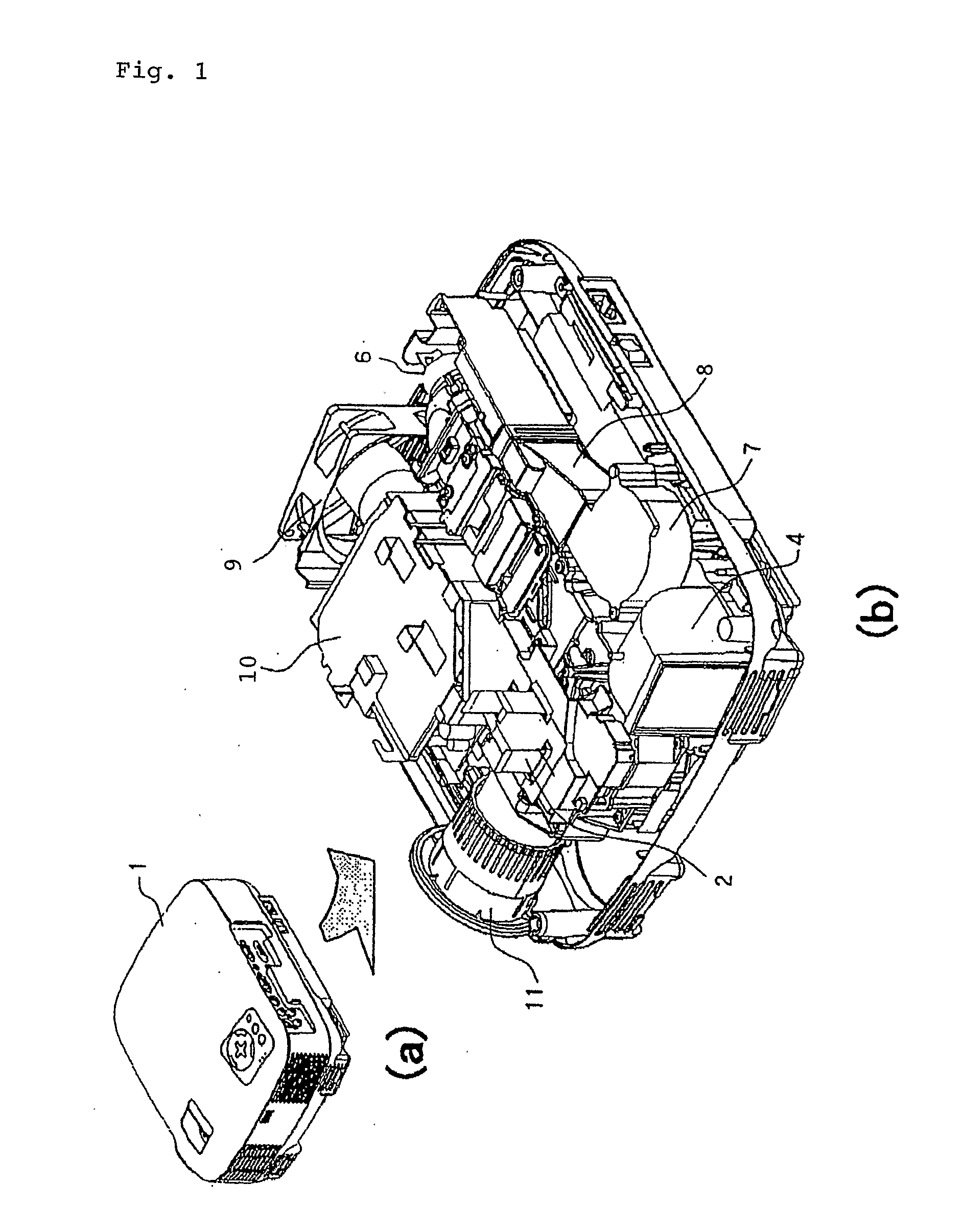
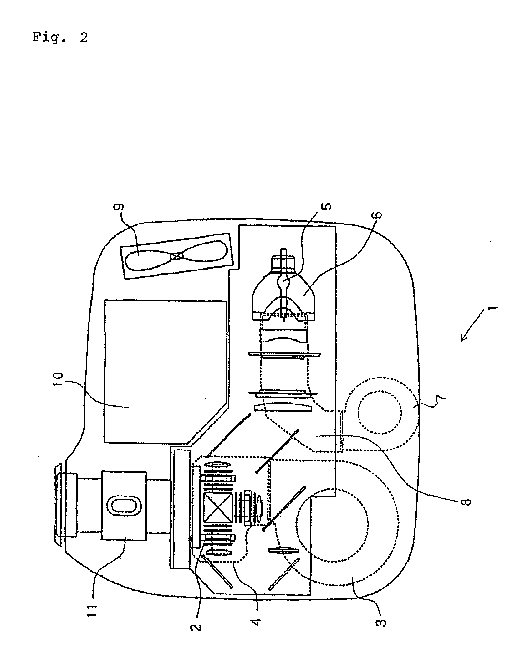
[0072]Next, an apparatus for cooling a heat generating spot of an electronic device according to an exemplary embodiment of the present invention will be described in terms of the configuration and operation with reference to the drawings. In this exemplary embodiment, for facilitating the understanding, the electronic device will be described as represented by a liquid crystal image display of a liquid crystal projector apparatus, and components such as an incident-side polarizing plate, a liquid crystal panel, and an exit-side polarizing plate which form a liquid crystal unit. However, the present invention is not limited to this exemplary embodiment, but may also be applied to a cooling apparatus or the like for an electronic device which includes a plurality of components, each of which includes surfaces opposite to each other with a spacing defined therebetween, where at least any of the surfaces opposite to each other is a heat generating spot, for example, heat generating spo...


PUM


Abstract

A silent cooling apparatus for effectively reducing the operating temperature of an electronic device includes a plurality of components which include surfaces opposite to each other with a spacing therebetween and have a heat generating spot on at least any of the surfaces opposite to each other, in a small and low-cost configuration. The apparatus for cooling a heat generating spot of an electronic device includes a cooling apparatus for forcedly air-cooling a heat generating spot of an electronic device which includes a plurality of components which are disposed side by side to have the same in-plane direction, and include heat generating spots within their surfaces. The cooling apparatus includes a first air cooling unit for feeding an air stream to the heat generating spot in an orientation of the in-plane direction, and a second air cooling unit for feeding an air stream to the heat generating spot in the in-plane direction in a different orientation from the air stream by the first air cooling unit.

Description

TECHNICAL FIELD[0001]The present invention relates to an apparatus for cooling a heat generating spot (area) of an electronic device, a cooling method therefor, and a liquid crystal projector apparatus, and more particularly, to an apparatus for cooling a heat generating spot (area) of an electronic device, with two cooling units which feed air streams that collide with each other on a cooling plane, a cooling method therefor, and a liquid-crystal projector apparatus which includes the apparatus for cooling a heat generating spot of an electronic device.BACKGROUND ART[0002]Apparatuses for cooling heat generating spots of electronic devices have been used in a variety of forms, and cooling apparatuses which rely on air for cooling have been developed in a variety of configurations for purposes of simplifying the configuration. A plurality of forced air cooling type cooling apparatuses are provided in projector apparatuses which are projection display devices currently widely used for...

Claims


Application Information

Patent Timeline
IPC IPC(8): G03B21/16H05K7/20
CPCG03B21/16
Inventor UTSUNOMIYA, MOTOYASU
Owner SHARP NEC DISPLAY SOLUTIONS LTD
Learn More