Capacitor

a capacitor and capacitor technology, applied in the field of capacitors, can solve the problems of insufficient welding points to increase the resistance of extracting an electrode, the quality of laser welding is susceptible to the extent, and the strength of the joining state after laser welding cannot be controlled, so as to achieve the effect of superior reliability, easy crushing, and stable joint parts

Inactive Publication Date: 2010-02-11
PANASONIC CORP
View PDF7 Cites 5 Cited by
  • Summary
  • Abstract
  • Description
  • Claims
  • Application Information

AI Technical Summary

Benefits of technology

[0012]The present invention provides a capacitor that solves conventional problems; joins the element to the terminal plate and metal case well accurately to present superior reliability in joining. The present invention includes an element with a pair of electrodes formed on its both ends; a metal case containing the element together with a driving electrolyte, with one electrode of the element joined to a joint part convexly provided on the inner bottom surface of the metal case; and a terminal plate with the other electrode of the element joined to a joint part convexly provided on the inner surface of the terminal plate, sealing the opening of the metal case. The capacitor is produced so that S1<S2<S3 holds, where S1 is the area of the joint part joined to the element, provided on the inner bottom surface of the metal case; S2 is the area of the joint part joined to the element, provided on the inner surface of the terminal plate; and S3 is the touching area of the inner bottom surface of the metal case and the element, excluding the joint part joined to the element, provided on the inner bottom surface of the metal case.
[0013]With the above-described structure, when t...

Problems solved by technology

Accordingly, the quality of laser welding is susceptible to the extent to which the end faces of element 11 at the positive and negative electrodes are crushed in a desired shape and desired dimensions.
However, the state where the end faces of element 11 at the positive and negative electrodes are crushed cannot be monitored from their appearance, which means the joining state after laser welding and its strength cannot be controlled.
As a result, a poor ...

Method used


Image

  • Capacitor
  • Capacitor
  • Capacitor

Examples


case 2

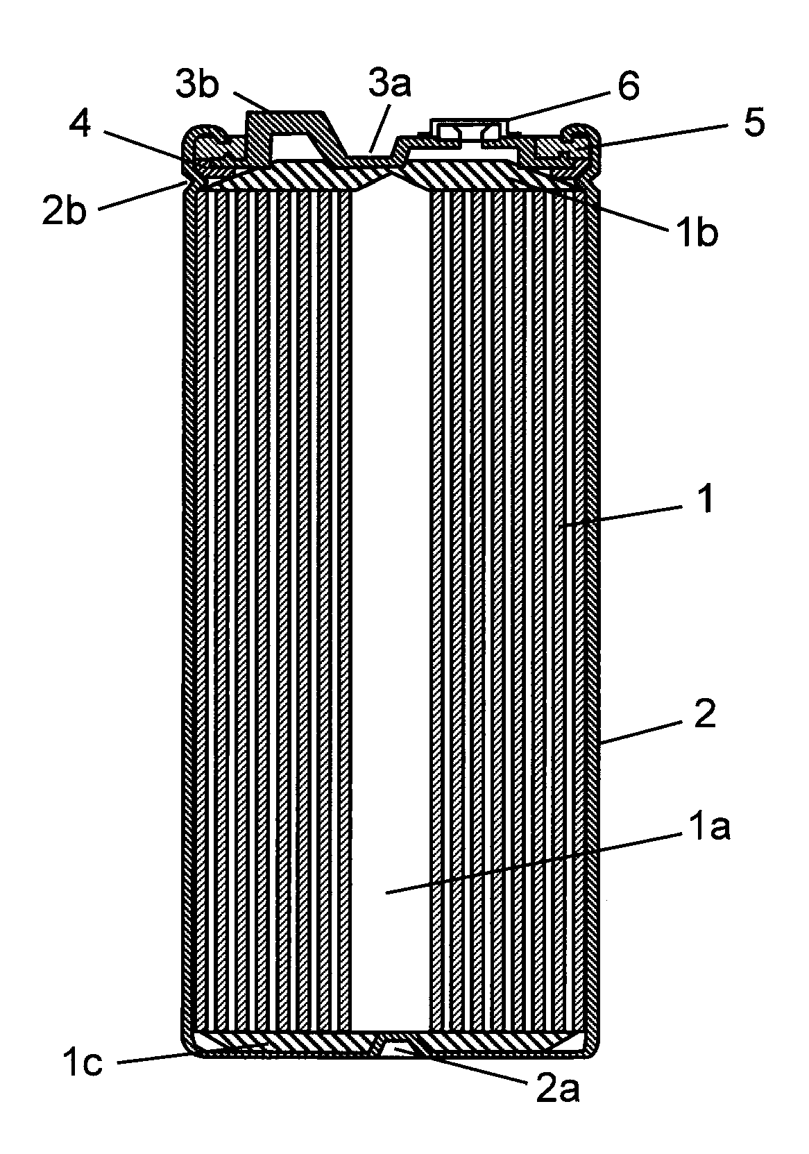
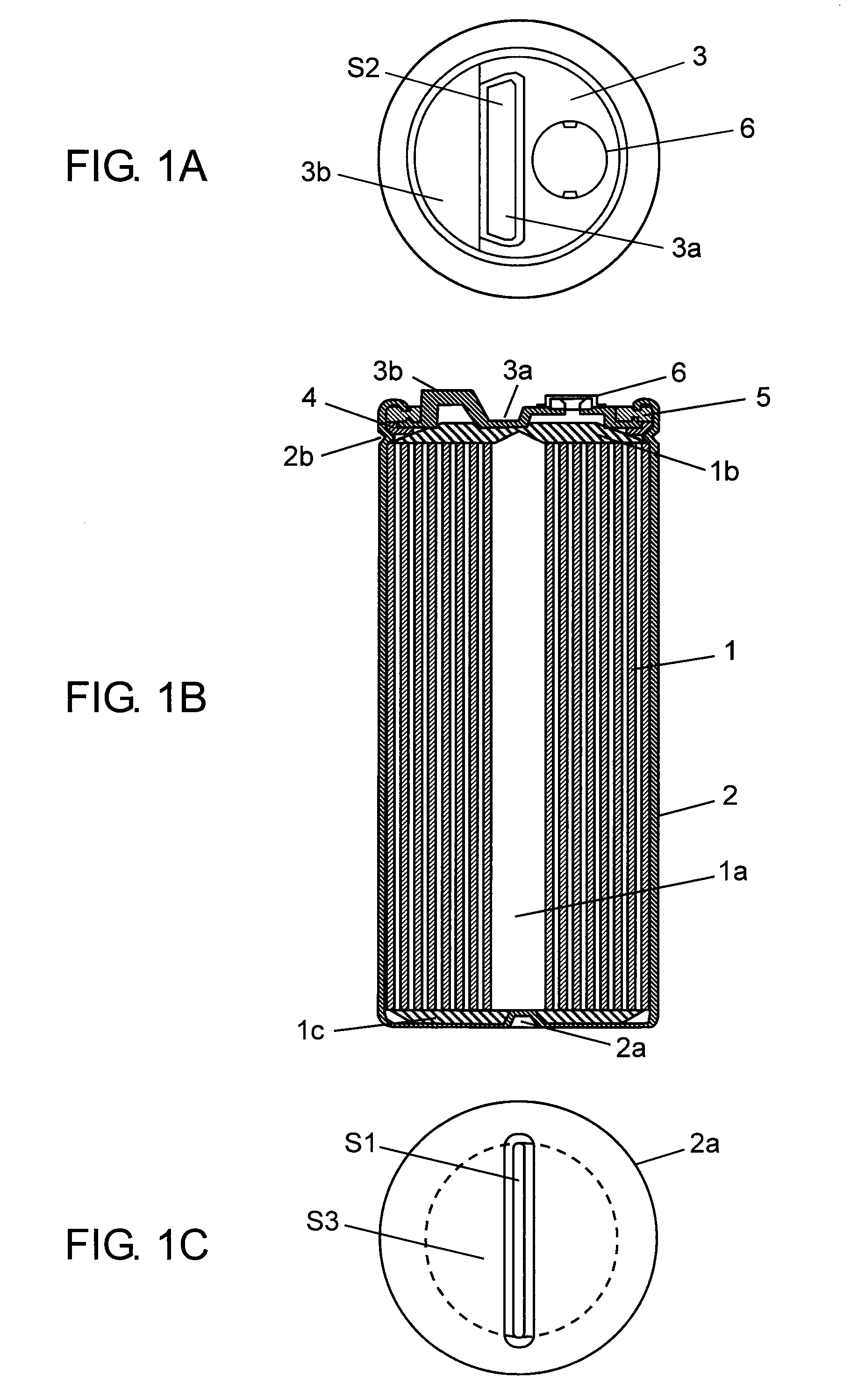
[0036]Metal case 2 is a bottomed, cylindrical case made of aluminum containing element 1 together with a driving electrolyte (not shown). Joint part 2a provided so as to convexly project in a strip shape on the inner bottom surface of this metal case 2 crushes cathode electrode 1c provided on one end face of element 1 inserted into metal case 2. This joint part 2a is laser-welded by being irradiated with laser light from the outside to join metal case 2 to cathode electrode 1c of element 1 mechanically and electrically.

[0037]Terminal plate 3 made of aluminum has joint part 3a placed so as to project in a strip shape roughly in the center of the inner surface of terminal plate 3 and terminal 3b for external connection. Joint part 3a crushes anode electrode 1b placed on the other end face of element 1, and this joint part 3a is laser-welded by being irradiated with laser light from the outside to join joint part 3a mechanically and electrically to extract the positive electrode of ele...


PUM


Abstract

The capacitor includes element (1) provided with electrodes at its both ends; metal case (2) with cathode electrode (1c) of element (1) joined to a joint part on the inner bottom surface of metal case (2), containing cathode electrode (1c); and a terminal plate with anode electrode (1b) of element (1) joined to a joint part on the inner surface of the terminal plate, sealing the opening of metal case (2). S1<S2<S3 holds, where S1 is the area of joint part (2a) of metal case (2); S2 is the area of joint part (3a) of the terminal plate; S3 is the touching area of the inner bottom surface and element (1), excluding joint part (2a) of metal case (2). When the terminal plate arranged on element (1) inside metal case (2) is pressurized, joint part (2a) of metal case (2) crushes cathode electrode (1c) of element (1), and then joint part (3a) of the terminal plate crushes anode electrode (1b) of element (1). Accordingly, both electrodes (1b, 1c) of element (1) can be laser-welded stably in a desired crush amount, thereby improving reliability of joining.

Description

TECHNICAL FIELD[0001]The present invention relates to a capacitor used for regeneration in electronic appliances and hybrid cars, and for power storage.BACKGROUND ART[0002]FIG. 2 is a developed view for showing the internal structure of element 11 (not shown) of this type of conventional capacitor. Element 11 has the following structure. That is, a pair of electrodes (positive and negative) have polarizable electrode layer 25 formed on collector 27 made of aluminum foil. The electrodes are displaced in the reverse direction to each other, separator 26 is interposed between them, and they are rolled up. A part of collector 27 where polarizable electrode layer 25 is not formed is an unformed part of the polarizable electrode layer, and part of it becomes positive electrode 21b and negative electrode 21c. FIG. 3 is a sectional view showing the structure of a conventional capacitor. In FIG. 3, element 11 has hollow 11a. From both end surfaces of element 11, positive and negative electro...

Claims


Application Information

Patent Timeline
IPC IPC(8): H01G9/155H01G9/02H01G2/02H01G9/00H01G11/00H01G11/66H01G11/68H01G11/70H01G11/78H01G11/82
CPCH01G9/0003H01G9/016H01G9/06H01G9/08H01G9/155Y02T10/7022H01G11/78H01G11/80H01G11/82Y02E60/13H01G11/74Y02T10/70
Inventor MIURA, TERUHISAKAWASAKI, SHUSAKU
Owner PANASONIC CORP
Why Eureka
Try Eureka