Method and device for producing a tomosynthetic 3D x-ray image

a tomosynthetic and 3d x-ray technology, applied in tomography, instruments, applications, etc., can solve the problem of severely attenuated individual dose emitted by such emitters, and achieve the effect of increasing the dos

Inactive Publication Date: 2010-02-11
SIEMENS AG
View PDF9 Cites 54 Cited by
  • Summary
  • Abstract
  • Description
  • Claims
  • Application Information

AI Technical Summary

Benefits of technology

[0010]An object of the present invention to provide a method and a device to generate a tomosynthetic 3D x-ray image which allow an exposure of an examination subject with a higher dose.

Problems solved by technology

The individual dose emitted by such emitters is therefore severely attenuated.

Method used


Image

  • Method and device for producing a tomosynthetic 3D x-ray image
  • Method and device for producing a tomosynthetic 3D x-ray image

Examples


Embodiment Construction

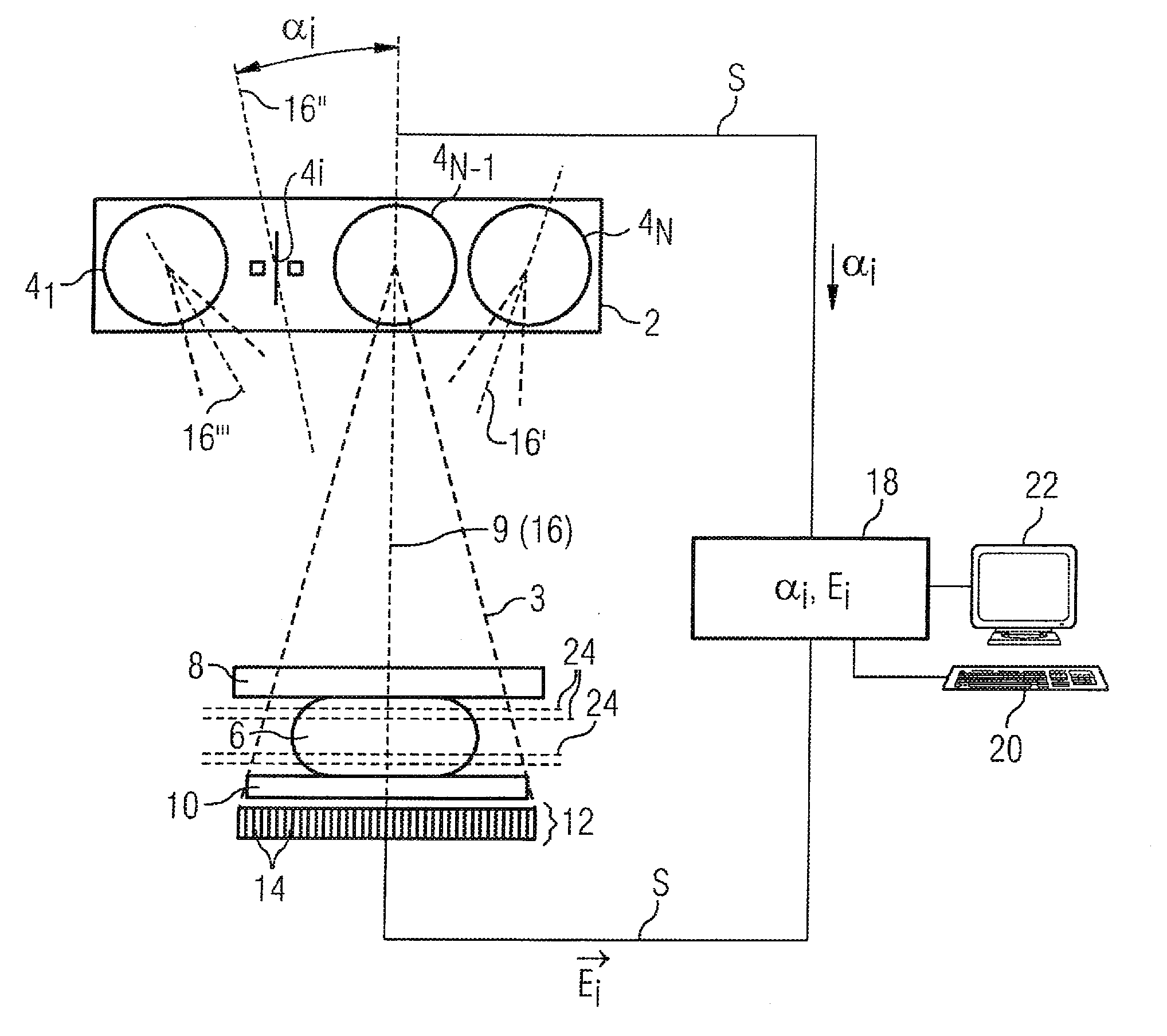
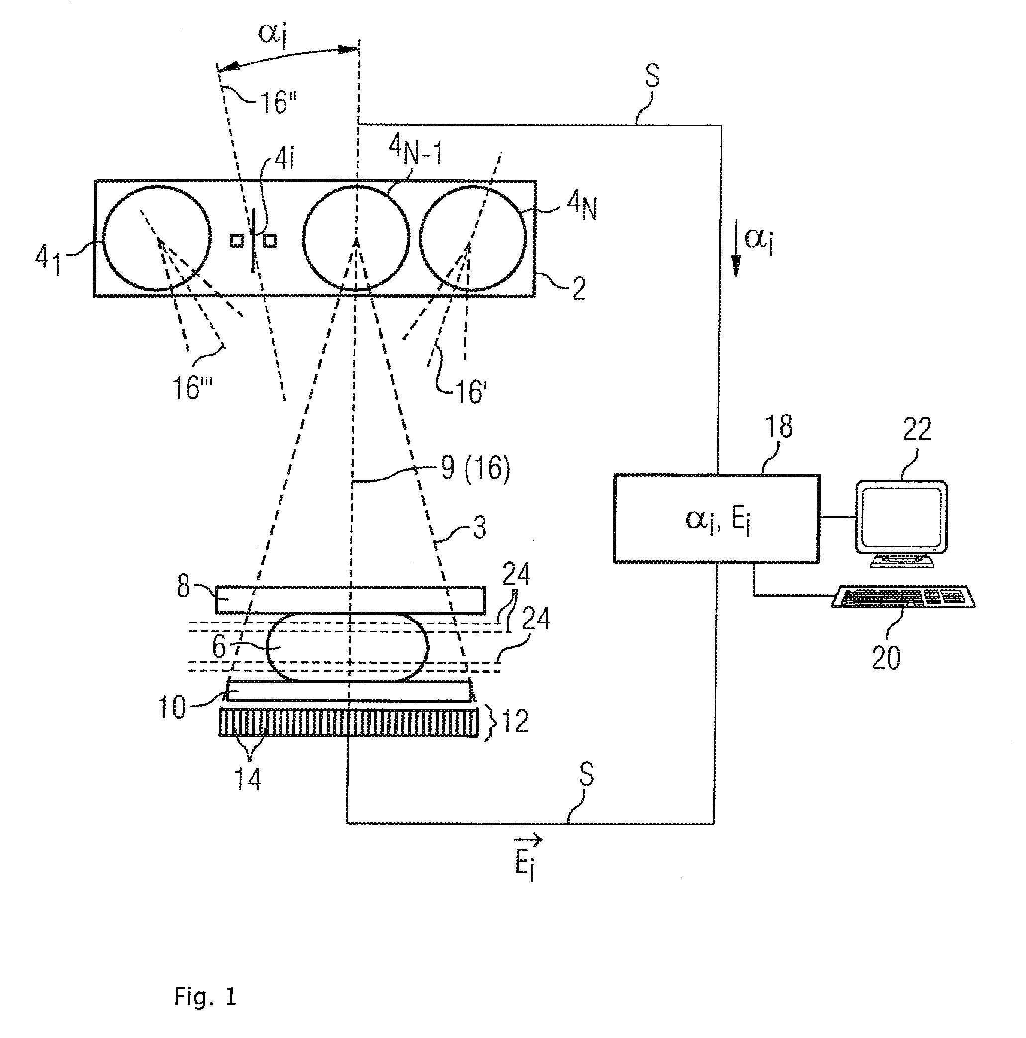
[0023]The FIGURE shows a mammography device with an x-ray source 2 that has a plurality of emitters 4. Shown is an x-ray source 2 with N emitters 41 through 4N. The individual emitters 4 are arranged in parallel in the manner of an array and generate x-rays 3 that expose an examination subject 6 (a female breast in the present case). The individual emitters 4 are arranged so that they expose the examination subject 6 from different angles α. The exposure direction 16″ of the i-th emitter 4i thereby encloses the angle αi with a surface normal 9. To adjust the exposure directions 16, 16′, 16″, 16″′, the emitters 4 can be arranged rotated slightly counter to one another in the x-ray source 2.

[0024]The examination subject 6 is fixed between a compression plate 8 and a bearing plate 10. An x-ray detector 12 that is composed of a number of individual detectors 14 in a matrix formation is located on the side of the examination subject 6 facing away from the x-ray source 2. The x-ray detect...


PUM


Abstract

In a method and device for producing a tomosynthetic 3D x-ray image, a number of 2D projection images of an examination subject are acquired using a fixed x-ray source. The x-ray source has multiple, individually controllable emitters that respectively emit a single x-ray dose from various different directions. The tomosynthetic 3D image is reconstructed from the individual 2D projection images, and at least one 2D projection image is composed of multiple individual images.

Description

BACKGROUND OF THE INVENTION[0001]1. Field of the Invention[0002]The invention concerns a method that is in particular suitable for mammography, as well as a device to generate a tomosynthetic 3D x-ray image. In such a tomosynthetic method, a number of x-ray images of an examination subject are acquired from different directions. The tomosynthetic 3D x-ray image is subsequently calculated from the 2D projection images obtained in this way.[0003]2. Description of the Prior Art[0004]A tomosynthetic 3D x-ray image is an image data set that is composed of slice images. Such an image data set acquired via reconstruction of 2D projection images is designated in the following as a tomosynthetic 3D x-ray image or 3D tomosynthesis image.[0005]Mammography concerns an x-ray examination of the breast with the goal of detecting malignant tumors at an optimally early stage. Through continuous improvement of imaging methods it is sought to generate x-ray images with greater significance in order to...

Claims


Application Information

Patent Timeline
Patent Type & Authority Applications(United States)
IPC IPC(8): G06K9/00H05G1/60
CPCA61B6/032A61B6/4028A61B6/405A61B6/4085H01J2235/068A61B6/482A61B6/502A61B6/542H01J2235/062A61B6/466
Inventor MERTELMEIER, THOMAS
Owner SIEMENS AG
Why Eureka
Try Eureka