

Method for producing a three-dimensionally shaped object
- Summary
- Abstract
- Description
- Claims
- Application Information
AI Technical Summary
Benefits of technology
Problems solved by technology
Method used
Image

Examples
first embodiment
[0029]A method for producing a three-dimensionally shaped object (hereinafter simply referred to as a “shaped object”) in accordance with a first embodiment of the present invention will now be described with reference to the accompanying drawings.
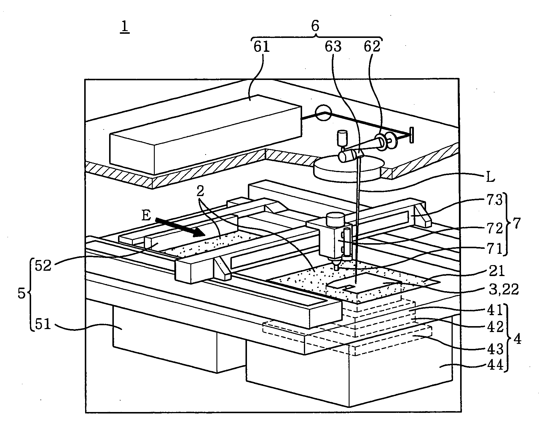
[0030]FIG. 1 shows the schematic configuration of a metal optical shaping machine (hereinafter simply referred to as an “optical shaping machine”) used in the production method of the first embodiment. The optical shaping machine 1 includes a shaping unit 4 for producing a shaped object 3 from a metallic powder (or a powdery material) 2, a powder layer forming unit 5 for forming a powder layer 21 by feeding the metallic powder 2 to the shaping unit 4, a solidifying unit 6 for forming a solidified layer 22 by irradiating a light beam L on a specified portion of the powder layer 21 and a cutting and removing unit 7 for cutting the peripheral portion of the shaped object 3.
[0031]The shaping unit 4 includes a substrate 41 on which the powder l...
second embodiment
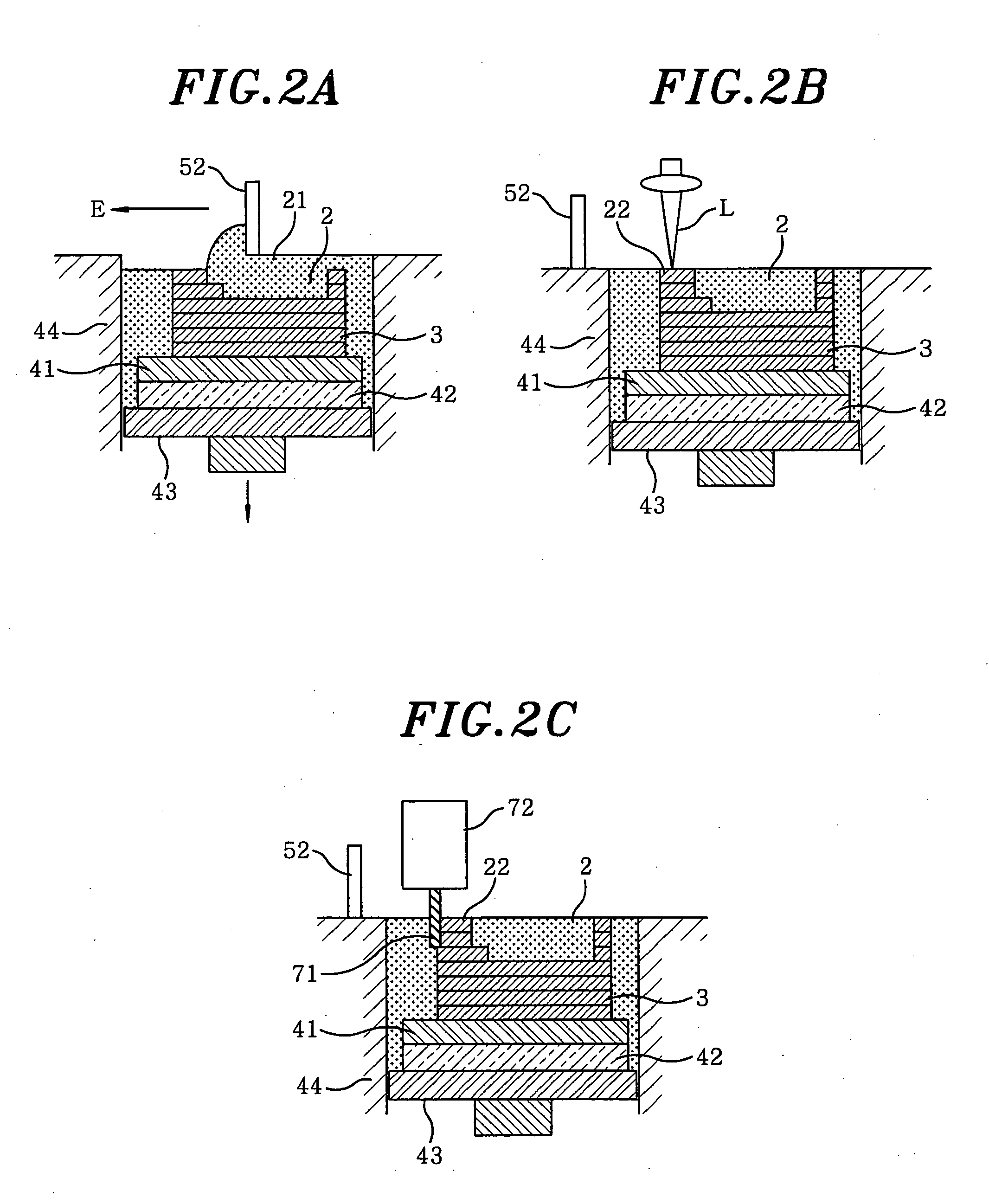
[0045]A method for producing a shaped object in accordance with a second embodiment of the present invention will now be described with reference to FIG. 8. Shown in FIG. 8 is the cross section of the optical shaping machine 1. In the present embodiment, the substrate 41 is directly mounted on the table 43 which in turn holds the peripheral portion of the substrate 41 in place. The central area of the rear surface of the substrate 41 is opened downwards. The optical shaping machine 1 includes a solidifying unit for irradiating the light beam L on the rear surface of the substrate 41. The control unit performs its control operation so that the light beam L is also irradiated on the rear surface of the substrate 41 while the powder layer 21 on the substrate 41 is irradiated by the light beam L in the solidified layer forming step. At this time, it is preferred that the light beam L is irradiated from below along substantially the same irradiation route as that of the powder layer 21. ...
PUM
| Property | Measurement | Unit |
|---|---|---|
| Stress optical coefficient | aaaaa | aaaaa |
| Deformation enthalpy | aaaaa | aaaaa |
Abstract
Description
Claims
Application Information