
Bioreactor with window

a bioreactor and window technology, applied in bioreactors/fermenters, biomass after-treatment, instruments, etc., can solve the problems of reducing the light transmissivity of the gas-introduction tube and standpipe that come into contact with the culture medium, requiring costly cleaning procedures, and requiring relatively laborious cleaning of the sample zone of the microscope prob

Inactive Publication Date: 2010-02-11
SARTORIUS STEDIM BIOTECH GMBH
View PDF12 Cites 27 Cited by
  • Summary
  • Abstract
  • Description
  • Claims
  • Application Information

AI Technical Summary

Benefits of technology

[0014]By virtue of the fact that the photocatalytic coating of the window that is touched by media can be activated by a light source, the adhering of media particles is prevented or particles or substances already adhering to the coating of the window are removed again by a light-initiated photocatalytic oxidation. Thus, a significantly improved service life of the window and thus a significantly improved long-term performance of the optical sensor systems are achieved.
[0020]Owing to their chemical resistance and their good thermal stability, the abovementioned glasses are particularly suitable for a coating in the dipping bath (dip coating) with subsequent calcination at a maximum temperature of 500° C.
[0022]The UV light required for the initiation of the photocatalytic oxidation can be supplied by a UV-LED, adjacent to the window, in a space-saving manner and relatively simply without major losses for the active coating. The wavelength used is particularly suitable for the chosen coating with TiO2 nanoparticles.
[0024]A measuring probe can be inserted into the probe receptacle without any risk of contamination, which measuring probe can be exchanged for an insertable UV-LED as necessary for self-cleaning of the window. It is particularly expedient, however, to arrange the UV-LED directly in the measuring probe, whereby mutual exchange can be dispensed with. Moreover, the UV illumination intervals can thereby be increased without any problems.
[0025]According to a further preferred embodiment of the invention, two windows arranged at a distance and parallel to one another delimit a cuvette gap of a measuring probe embodied as a transmission probe and projecting into the reactor interior, wherein each of the windows is assigned a UV-LED. In this case, an optical signal can be fed via a deflection prism to the first window and further via the cuvette gap, filled by the surrounding medium, via the second window to an optical evaluation unit. Particularly advantageously, the first window can be formed by a coated partial region of the deflection prism. This is especially space-saving.
[0029]Particularly when using bioreactors as disposable bioreactors, such as are often used with a flexible wall as bags, the use of a window coated according to the invention is of great importance since the service life of the entire bioreactor is considerably increased.

Problems solved by technology

The known apparatus, which has proved to be worthwhile in principle, has the disadvantage that the sample zone of the microscope probe that comes into contact with the medium to be examined has to be cleaned relatively laboriously by means of cleaning liquid supplied externally.
The known apparatus, which has proved to be worthwhile in principle, has the disadvantage that the light transmissivity of the gas-introduction tubes and standpipe that come into contact with the culture medium is reduced by deposits on the inner sides facing the reactor interiors over the course of the operating period and necessitate costly cleaning procedures.

Method used


Image

  • Bioreactor with window
  • Bioreactor with window
  • Bioreactor with window

Examples


Embodiment Construction

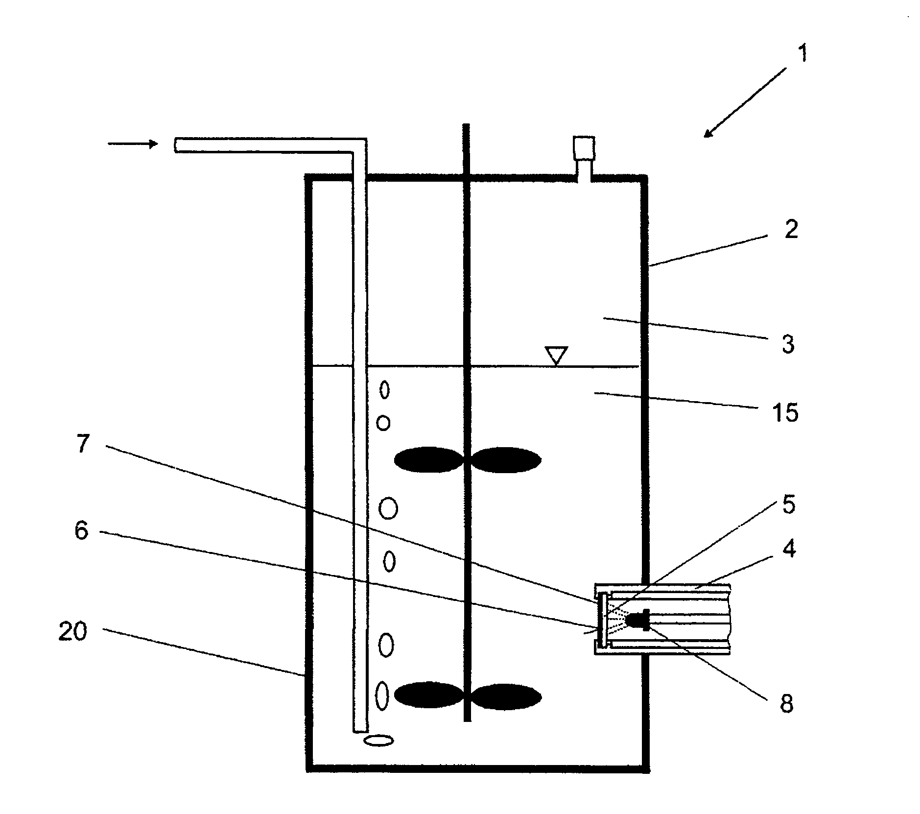
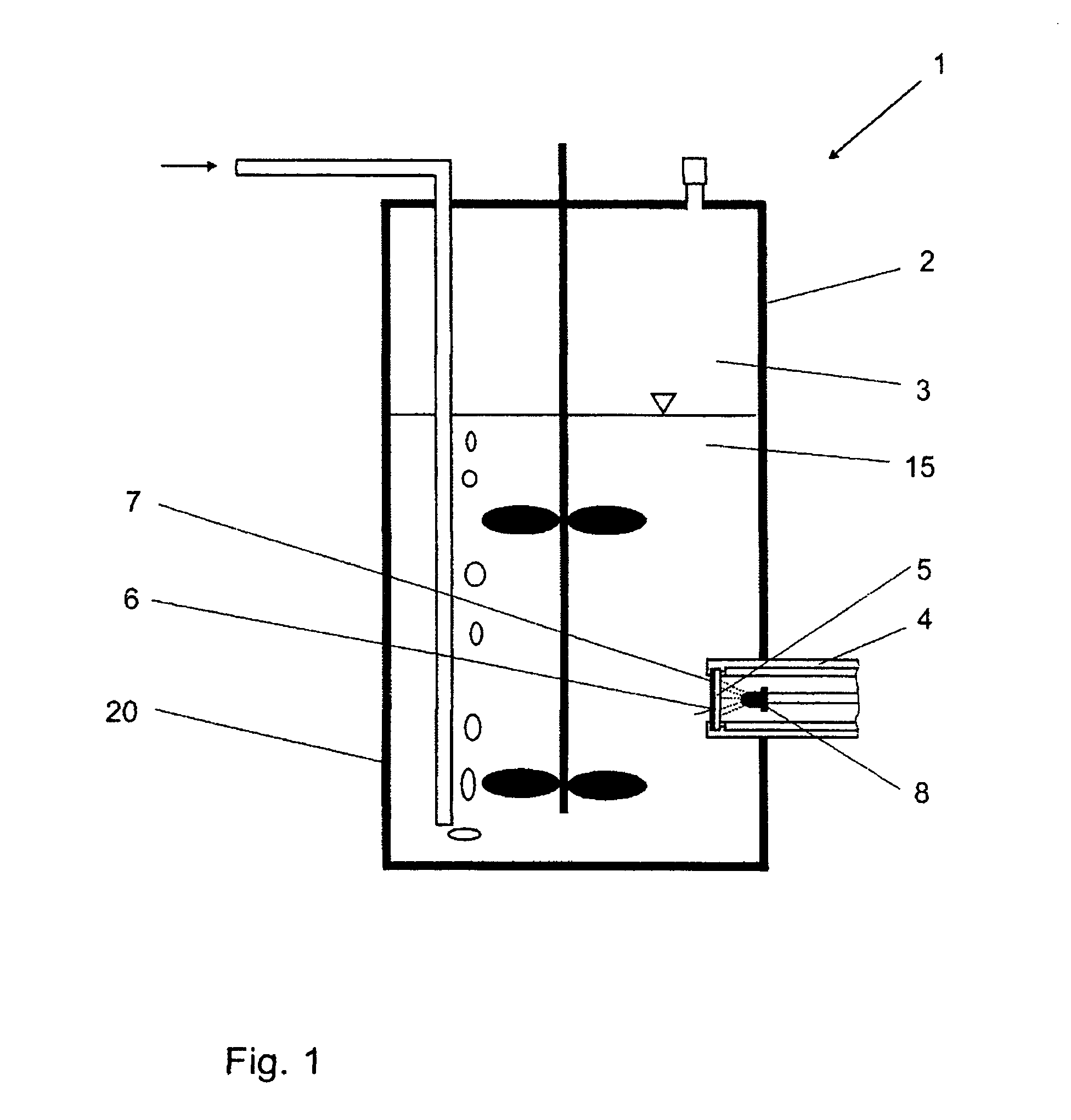
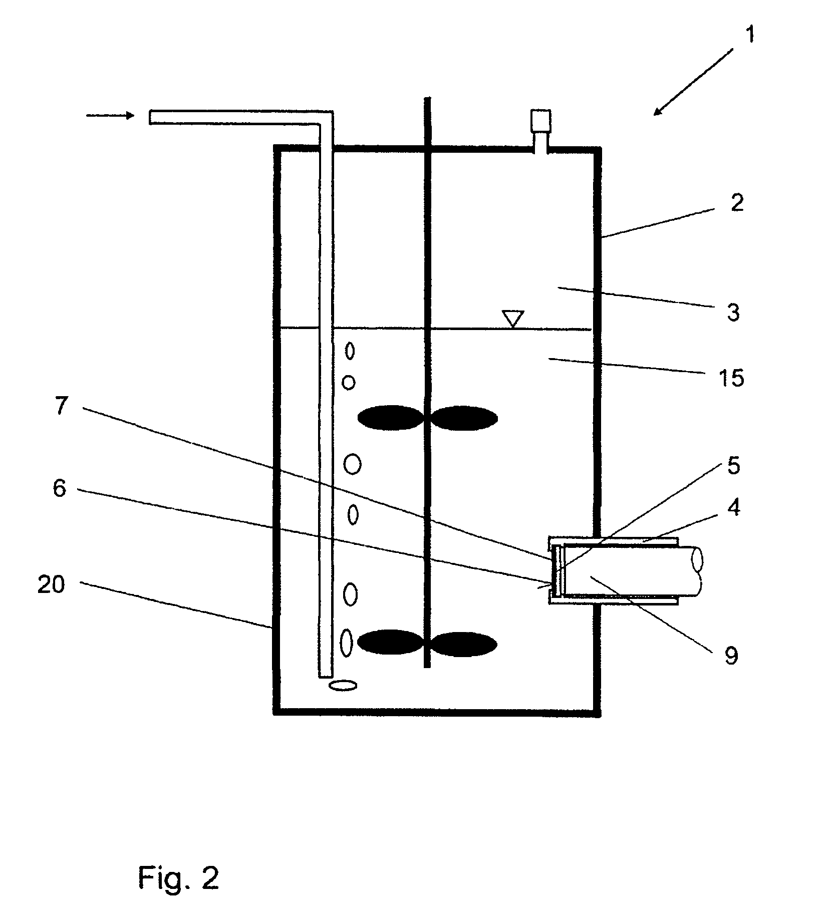
[0035]Turning to FIG. 1, a bioreactor 1 essentially comprises a reactor interior 3 enclosed by a flexible wall 2, and a probe receptacle 4 with an optical window 5.

[0036]The probe receptacle 4 of the embodiment according to FIGS. 1 and 2 is closed off toward the reactor interior 3 by the optical window 5, which has a photocatalytic coating 7 on its inner side 6 facing the reactor interior 3. The coating is embodied as a nanocrystalline titanium dioxide coating (TiO2). The optical window 5 is composed of a borosilicate glass.

[0037]A UV-LED 8 can be inserted into the probe receptacle 4 in order to activate the photocatalytic coating 7, and a measuring probe 9 can be inserted in order to carry out the measuring operation. However, the UV-LED 8 can also be integrated into the measuring probe 9.

[0038]In accordance with the exemplary embodiment in FIGS. 3 and 4, the measuring probe 9 is embodied as a transmission probe 10, which projects by its free end 11 into the reactor interior 3 of t...


PUM


Abstract

Bioreactor having at least one transparent window (5, 12, 13), the inner side (6) of which can be touched by a medium that can be arranged in a reactor interior (3), wherein the window (5, 12, 13) has a photocatalytic coating (7) on its inner side (6) facing the reactor interior (3), which coating can be activated by at least one light source from the outer side remote from the inner side (6).

Description

BACKGROUND OF THE INVENTION[0001]1. Field of the Invention[0002]The invention relates to a bioreactor having at least one transparent window, the inner side of which can be touched by a medium that can be arranged in a reactor interior.[0003]2. Description of the Related Art[0004]Noninvasive optical measurement methods are increasingly gaining in importance for the online monitoring of bioprocesses. The particular advantage of these measurement methods is based on the fact that suitable sensor systems can be coupled via optical windows to bioreactors or fermenters, for example, whereby any risk of contamination arising as a result of offline sampling is precluded. A further advantage is that optical measurement methods generally operate very rapidly and continuously and, on account of the weak interactions between electromagnetic radiation and matter, nondestructively.[0005]Particular requirements are made of the optical windows required for these measurement methods. Firstly, they ...

Claims


Application Information

Patent Timeline
IPC IPC(8): C12M3/00
CPCC12M23/22C12M41/36C12M27/02G01N2021/8528G01N2021/8521G01N21/8507G01N21/33
Inventor BAHNEMANN, DETLEFBAUMFALK, REINHARDRIECHERS, DANIELSCHEPER, THOMAS
Owner SARTORIUS STEDIM BIOTECH GMBH
Learn More