Rotating stent system for side branch access and protection and method of using same

a stent and side branch technology, applied in the field of stents and stent delivery systems, can solve the problems of ineffective devices and methods for achieving proper angular orientation, site inadequate treatment of stents, and inability to properly place and position stents,

Inactive Publication Date: 2010-02-11
GUMM DARREL C
View PDF53 Cites 28 Cited by
  • Summary
  • Abstract
  • Description
  • Claims
  • Application Information

AI Technical Summary

Benefits of technology

[0017]The present invention contemplates a new and improved apparatus and method that improves the orientation of a stent by providing a more exact placement of the stent relative to the side branch passage. This, in turn, may lead to better protection of the side branch passage. The present invention has the potential for improvement in trackability of the stent delivery system.
[0020]A feature of some embodiments may be that at the time of positioning the stent, the stent will be properly oriented relative to the side branch, i.e., a stent delivery system and method that correctly positions the stent in a bifurcated passage.
[0022]Another feature may be proper alignment of the stent delivery system in a bifurcated passage to achieve correct circumferential orientation relative to a side branch passage, and securing the desired orientation.

Problems solved by technology

Although efforts have been made to use a stent at bifurcations, these sites have previously been inadequately treated by a stent.
However, problems are still encountered in orienting the stent relative to the side branch at the bifurcation of the main and branch passages.
These devices and methods of achieving proper angular orientation have not been shown to be effective in properly placing and positioning the stent.
As will be appreciated and understood by those skilled in the art, improper placement of the stent with respect to its rotational or circumferential orientation, or its longitudinal placement, could lead to obstruction of the side branch passage.
Commercially available devices do not maintain side branch access at the time of stent deployment.
This results in the potential for plaque shift and occlusion of the side branch passage.

Method used


Image

  • Rotating stent system for side branch access and protection and method of using same
  • Rotating stent system for side branch access and protection and method of using same
  • Rotating stent system for side branch access and protection and method of using same

Examples


Embodiment Construction

[0035]While this invention may be embodied in many different forms, there are described in detail herein specific preferred embodiments of the invention. This description is an exemplification of the principles of the invention and is not intended to limit the invention to the particular embodiments illustrated.

[0036]For the purposes of this disclosure, like reference numerals in the figures shall refer to like features unless otherwise indicated.

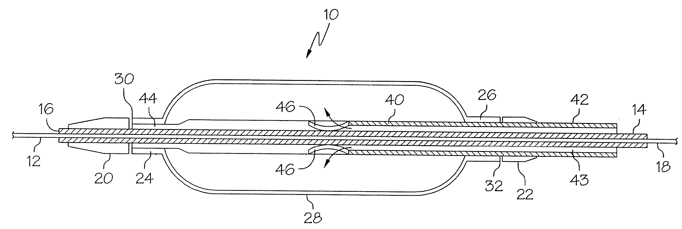
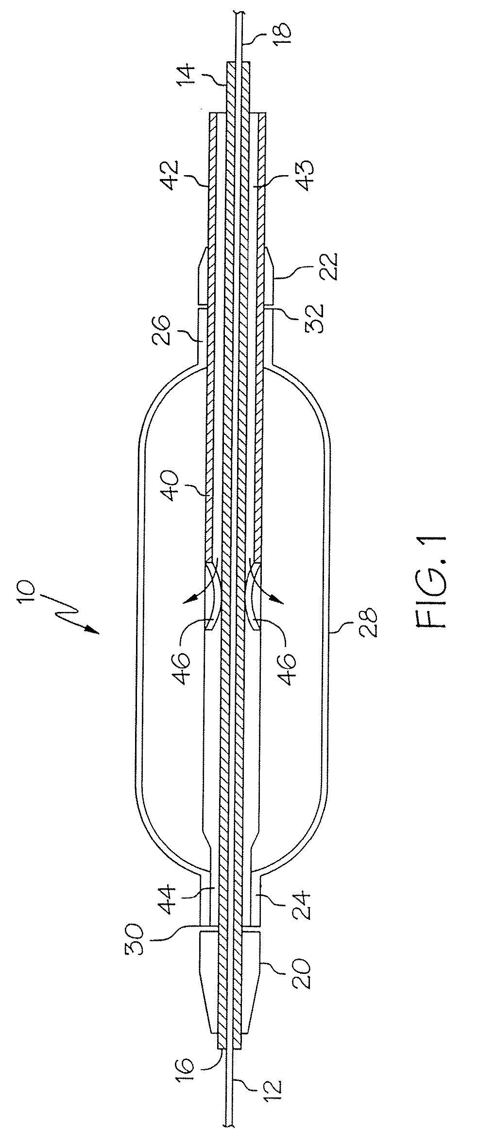
[0037]Referring now to the drawings wherein the showings are for the purposes of illustrating the preferred embodiments of the invention only and not for purposes of limiting same, FIG. 1 shows a stent delivery system or assembly 10. Assembly 10 includes a first guide member, or main guide wire 12 that extends axially through a first hollow or tubular member 14. The first hollow member 14 will also be identified as a main hypotube, although it will be appreciated that the particular shape or configuration of this component may change from t...


PUM


Abstract

A catheter assembly and method of use comprises advancing a catheter having a rotatably mounted balloon relative to the primary guide wire to a vessel bifurcation along first and second guide wires.

Description

CROSS-REFERENCE TO RELATED APPLICATIONS[0001]This application is a continuation of U.S. application Ser. No. 10 / 226,362, filed Aug. 22, 2002, titled “ROTATING STENT DELIVERY SYSTEM FOR SIDE BRANCH ACCESS AND PROTECTION AND METHODS OF USING”, which claims priority to U.S. Provisional Application 60 / 314,467, filed Aug. 23, 2001, all of which are hereby incorporated by reference in their entirety.BACKGROUND OF THE INVENTION[0002]1. Field of the Invention[0003]At least one embodiment of the present invention is directed to the field of stents and stent delivery systems used to treat stenoses, and more particularly to stenoses at a bifurcation of a passage[0004]2. Description of the Related Art[0005]Stent systems are widely used in the treatment of stenoses. Intravascular stents are used in coronary, renal, and carotid arteries, for example, to maintain an open passage through the artery. In patients whose coronary heart disease consists of focal lesions, stents have proven effective. Fo...

Claims


Application Information

Patent Timeline
Patent Type & Authority Applications(United States)
IPC IPC(8): A61F11/00A61M29/00A61F2/82
CPCA61F2/856A61F2/954A61M2025/1045A61F2002/821A61M2025/1056A61F2/958
Inventor GUMM, DARREL C.
Owner GUMM DARREL C
Why Eureka
Try Eureka