Torque controller for on-vehicle power generator

Inactive Publication Date: 2010-02-11
DENSO CORP
View PDF3 Cites 44 Cited by
  • Summary
  • Abstract
  • Description
  • Claims
  • Application Information

AI Technical Summary

Benefits of technology

[0010]When both the accelerator operation and the brake operation are performed at the same time, the torque reducing means reduces the torque of the power generator according to an output value of the brake information obtaining

Problems solved by technology

When the accelerator pedal is stepped by the driver and then the accelerator pedal is released, the accelerator pedal may not return to the original position due to a floor carpet.
Furthermore, the negative pressure downstream of the throttle valve becomes small.
When a brake operation is performed in a vehicle equipped with the brake booster, the brake booster can not be operated normally and the brake torque can not be obtained sufficiently.
A

Method used


Image

  • Torque controller for on-vehicle power generator
  • Torque controller for on-vehicle power generator
  • Torque controller for on-vehicle power generator

Examples


Embodiment Construction

[0017]An embodiment of a torque controller applied to a gasoline engine will be described hereinafter.

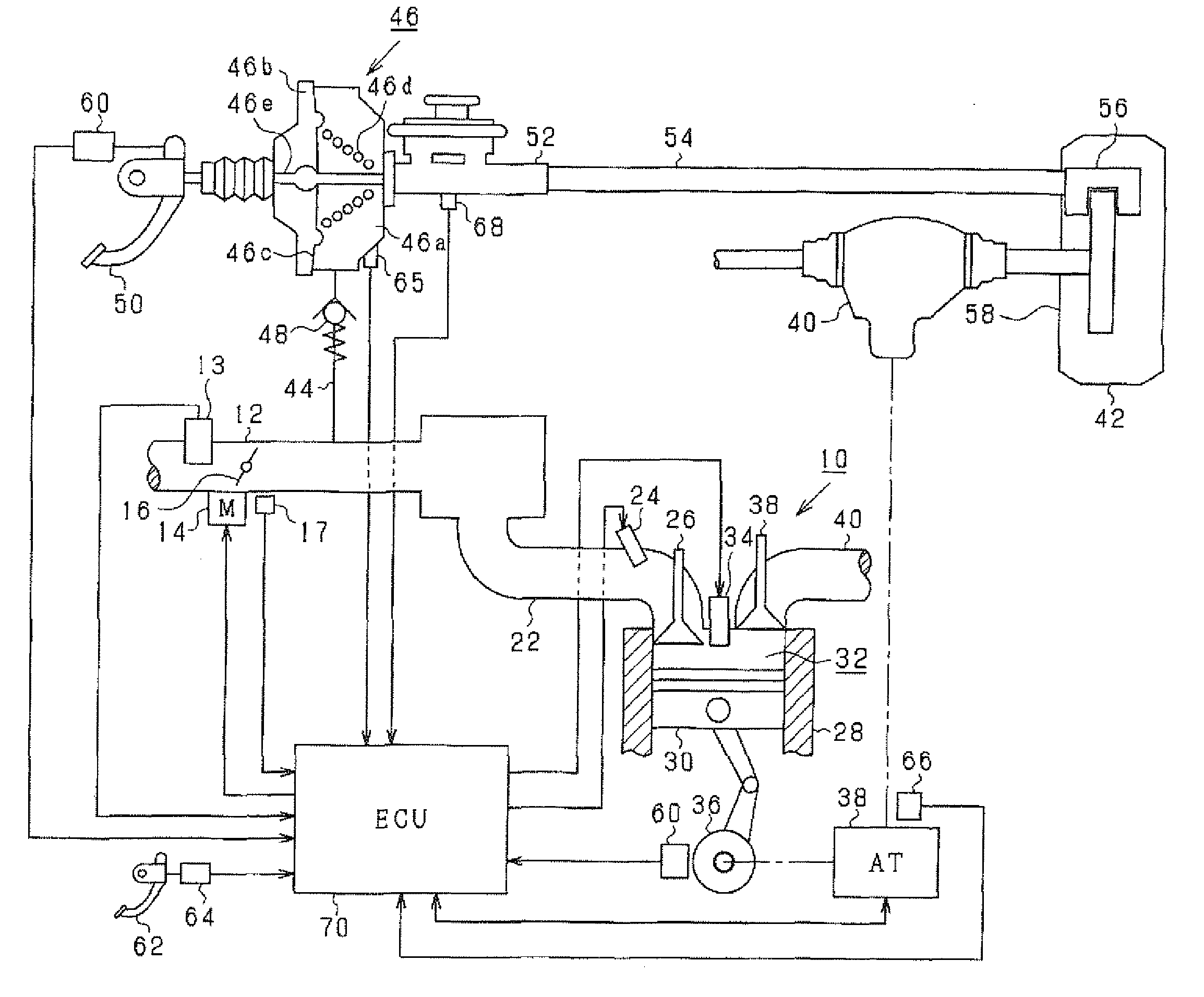
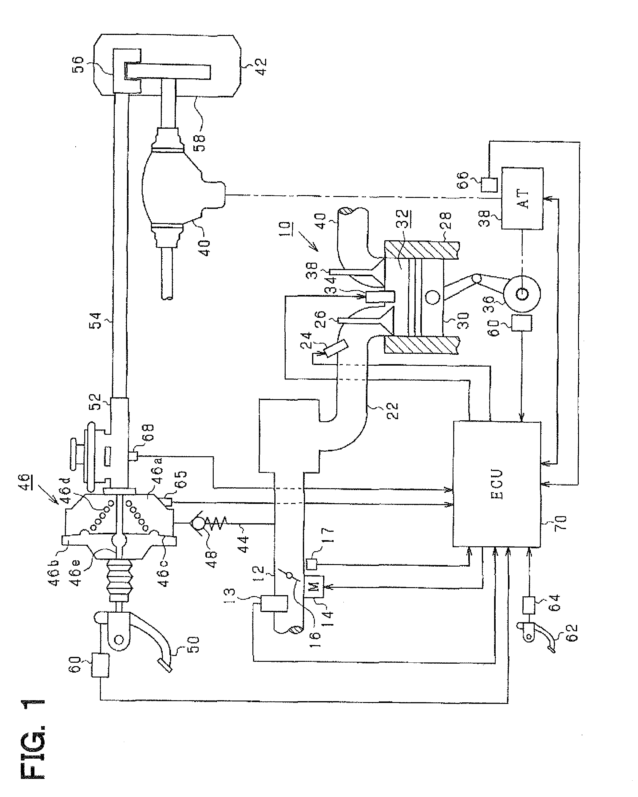
[0018]FIG. 1 shows an entire structure of a brake system and an engine control system in the present embodiment. An air flow meter 13 detecting an intake air quantity is provided in an intake pipe 12. A throttle valve 16 is provided downstream of the air flow meter 13. The throttle valve 16 is electrically driven by a throttle actuator 14 such as a DC motor. A position of the throttle valve 16 is detected by a throttle position sensor 17 provided in the throttle actuator 14. An intake manifold 22 is connected to the intake pipe 12 downstream of the throttle valve 16. The intake manifold 22 introduces intake air into each cylinder. A fuel injector 24 is provided at a vicinity of an intake air port of the intake manifold 22 of each cylinder to inject fuel into the cylinder.

[0019]An intake valve 26 is provided at the intake port of the engine 10. When the intake valve 26 is opened, eac...


PUM


Abstract

When it is determined that accelerator operation and brake operation are performed at the same time based on the output values of an accelerator sensor and a stop lamp switch, a torque of an engine is reduced based on a brake pedal force which is computed based on a pressure in a negative pressure chamber of a master bag and a brake oil pressure.

Description

CROSS-REFERENCE TO RELATED APPLICATION[0001]This application is based on Japanese Patent Application No. 2008-202729 filed on Aug. 6, 2008, the disclosure of which is incorporated herein by reference.FIELD OF THE INVENTION[0002]The present invention relates to a torque controller for on-vehicle power generator.BACKGROUND OF THE INVENTION[0003]In a vehicle applied to such a torque controller, the vehicle includes a brake booster which assists the brake pedal force. The brake booster assists a brake pedal force of a driver by use of a differential pressure between the negative pressure downstream of a throttle valve in the intake pipe and an atmospheric pressure, so that the brake torque is increased.[0004]When the accelerator pedal is stepped by the driver and then the accelerator pedal is released, the accelerator pedal may not return to the original position due to a floor carpet. In such a case, the throttle valve opening becomes larger than a case where the accelerator pedal is r...

Claims


Application Information

Patent Timeline
IPC IPC(8): G06F19/00B60T8/00B60T17/00F02D9/02F02D11/10F02D29/02F02D45/00
CPCB60W10/06B60W10/184B60W30/18109B60W2510/0671B60W2540/10B60W2540/12F02D2250/41B60W2710/105F02D11/107F02D41/1497F02D2200/602F02D2250/18B60W2710/0666
Inventor HAYAMI, TOSHIFUMI
Owner DENSO CORP
Why Eureka
Try Eureka