Combustion Chamber for Burning Solid Fuels

a combustion chamber and solid fuel technology, applied in the direction of solid fuel combustion, combustion types, lighting and heating apparatus, etc., can solve the problems of inconvenient use in comparison with oil or gas burning devices, inefficient burning of cord wood in conventional combustion chambers, and slowing down the increase of carbon dioxide levels in the atmospher

Active Publication Date: 2010-02-18
DUIGNAN FRANCIS DONAL +1
View PDF12 Cites 16 Cited by
  • Summary
  • Abstract
  • Description
  • Claims
  • Application Information

AI Technical Summary

Benefits of technology

[0044]An advantage of this arrangement is that when a low output is required the combustion chamber can be moved closer to the inner heat transferring surface. This has the effect of restrict

Problems solved by technology

Furthermore, use of renewable fuels in such devices could slow down the increase in carbon dioxide levels in the atmosphere.
However, cord wood burns inefficiently in conventional combustion chambers and is inconvenient to use in comparison with oil or gas burning devices.
However, again, biomass fuel tends to burn inefficiently in conventional devices and this is due to its high volatiles content.
Much of the heat is released into the burning gases (the flames) and is lost up the chimney or flue.
Another reaso

Method used


Image

  • Combustion Chamber for Burning Solid Fuels
  • Combustion Chamber for Burning Solid Fuels
  • Combustion Chamber for Burning Solid Fuels

Examples


second embodiment

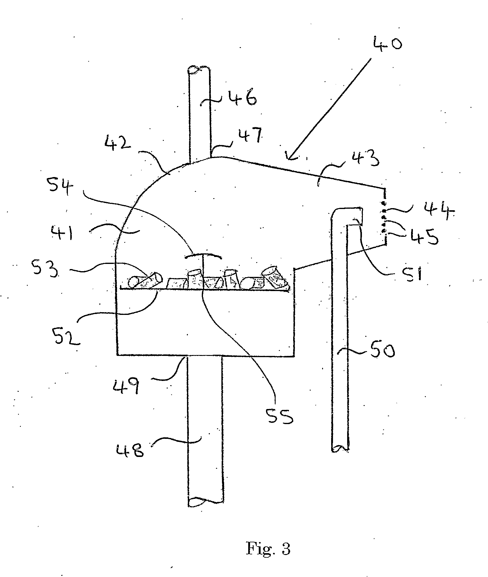
[0061]Referring to FIG. 3 there is illustrated, generally at 40, a combustion chamber in accordance with the invention. The combustion chamber 40 is designed to burn wood pellets and to provide a blown flame and is suitable for use as a replacement for an oil burner in an oil-fired heating boiler.

[0062]The combustion chamber 40 has an enclosed hollow body 41, which has a generally circular cross-section and a domed top section 42.

[0063]A frusto-conical section 43 extends laterally from the top section 42 and terminates in a volatiles outlet 44 having a plurality of apertures 45. A fuel inlet 46 is located at point 47 on the top section 42 and a primary air inlet 48 is located at point 49 on the body section 41.

[0064]A secondary air inlet 50 is mounted in the frusto-conical section 43 and is positioned such that a secondary air nozzle 51 is located, within the hollow body 41, adjacent the volatiles outlet 44.

[0065]A grate 52 is mounted within the hollow body 41 and supports the wood ...

third embodiment

[0067]Referring to FIG. 4 there illustrated generally at 60, a combustion chamber in accordance with the invention, the combustion chamber 60 having an enclosed hollow body 61, which is generally circular in cross-section. The hollow body 61 has a cylindrical wall section 62 and a top section 63 at end 64 of the cylindrical section 62.

[0068]A volatiles outlet 65 is mounted in the top section 63 and has a plurality of apertures 66 therein. A pipe 67 passes through a central opening 68 in the top section 63. The pipe 67 serves as a fuel inlet 69 and a secondary air inlet 70.

[0069]A grate 71 is mounted within the hollow body 6 land supports the wood pellets 72 to be burnt.

[0070]A primary air inlet 73 is mounted at the bottom end 74 of the hollow body 61.

[0071]In the embodiment illustrated the combustion chamber 60 forms part of a fire chamber, shown generally at 75, in accordance with the invention. The fire chamber 75 has a water jacket 76 having an inner heat transferring surface 77 ...


PUM


Abstract

A combustion chamber (10) for burning solid fuels having a high volatiles content has a hollow body (11) with a cylindrical wall section (12) and a top section (13) located at end (14) of the cylindrical wall section (12). The hollow body (11) has a primary air inlet (20), a fuel inlet (23) and four volatiles outlets (25) (one shown), mounted therein. Each volatiles outlet (25) has a plurality of apertures (26) of differing sizes arranged in a plate (27). In use, the burning volatiles exit the apertures (26) in a turbulent flow resulting in efficient combustion of the volatiles. Additionally, a heat transferring surface (33) on a water jacket (32) is shaped around the combustion chamber (10) so as to define a channel (34) there between. This arrangement results in an efficient transfer of heat from the turbulent flow of volatiles, which is forced to circulate around the channel (34).

Description

TECHNICAL FIELD[0001]This invention relates to a combustion chamber for burning solid fuels having a volatiles content and, in particular, to a combustion chamber for burning solid fuels having a high volatiles content, and also to a fire chamber incorporating such a combustion chamber.[0002]By solid fuels having a high volatiles content in this context is meant solid fuels such as wood pellets, pellets made from switchgrass, miscanthus, maize stalks, straw or the like, and nut shells such as almond shells, all collectively referred to as solid biomass fuels, and also fossil fuels such as peat or bituminous coal. In contrast, an example of a low volatiles solid fuel would be anthracite coal.BACKGROUND ART[0003]In recent years, worldwide concern has arisen relating to climatic changes ascribed to the increase in atmospheric carbon dioxide released by fossil fuels. The price of such fuels has been increasing, and projections as to the remaining world supplies of such fossil fuels have...

Claims


Application Information

Patent Timeline
IPC IPC(8): F23B80/04F23B60/02F23B50/12F23B90/00
CPCF23B1/08F23B1/26F23B80/04F23B50/12F23B60/02F23B1/36F23B5/04F23B10/02F23L9/04
Inventor DUIGNAN, FRANCIS DONALO'HALLORAN, MICHAEL PATRICK
Owner DUIGNAN FRANCIS DONAL
Why Eureka
Try Eureka