Light-emitting diode illumination apparatus

Inactive Publication Date: 2010-02-18
CHANG WAH ELECTROMATERIALS INC
View PDF4 Cites 14 Cited by
  • Summary
  • Abstract
  • Description
  • Claims
  • Application Information

AI Technical Summary

Benefits of technology

[0007]The invention provides an LED illumination apparatus havi

Problems solved by technology

Generally speaking, high-power LEDs all encounter heat dissipation problems.
When an LED is operated in an overly high temperature, the brightness of the LED illumination apparatus may be reduced and the lifespan of the LE

Method used


Image

  • Light-emitting diode illumination apparatus
  • Light-emitting diode illumination apparatus
  • Light-emitting diode illumination apparatus

Examples


first embodiment

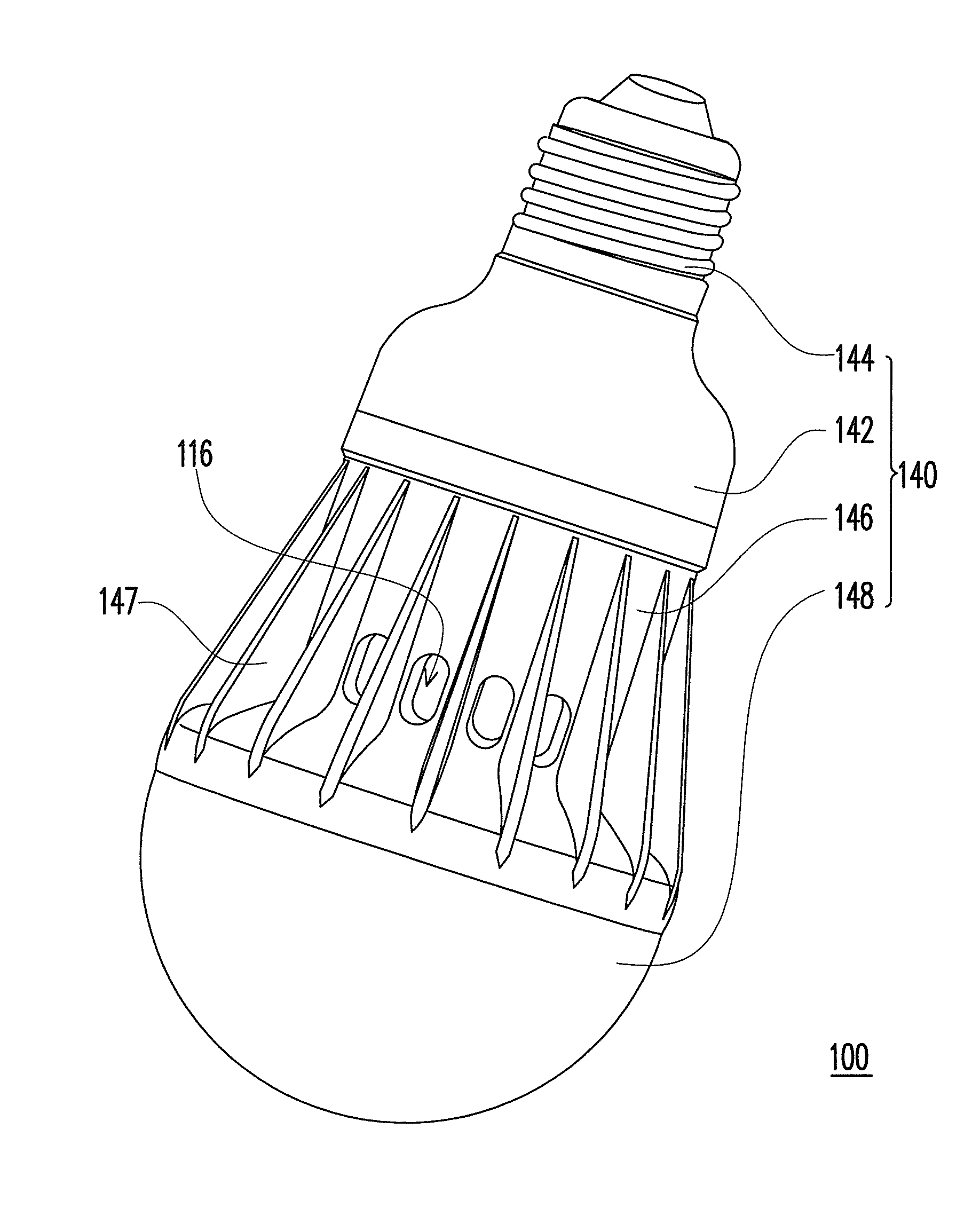
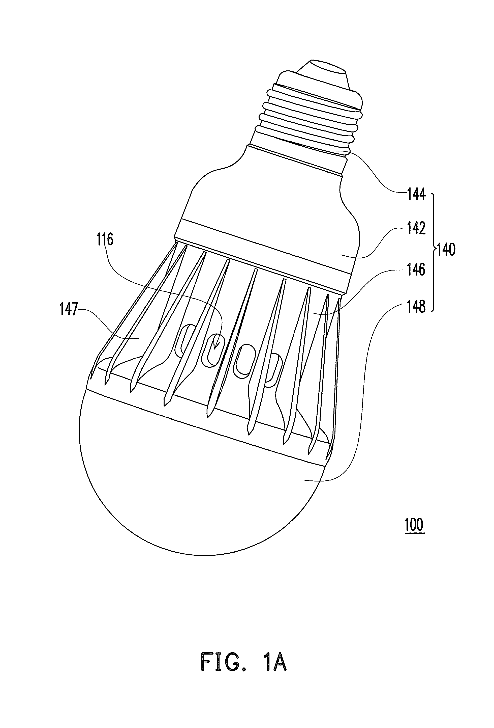
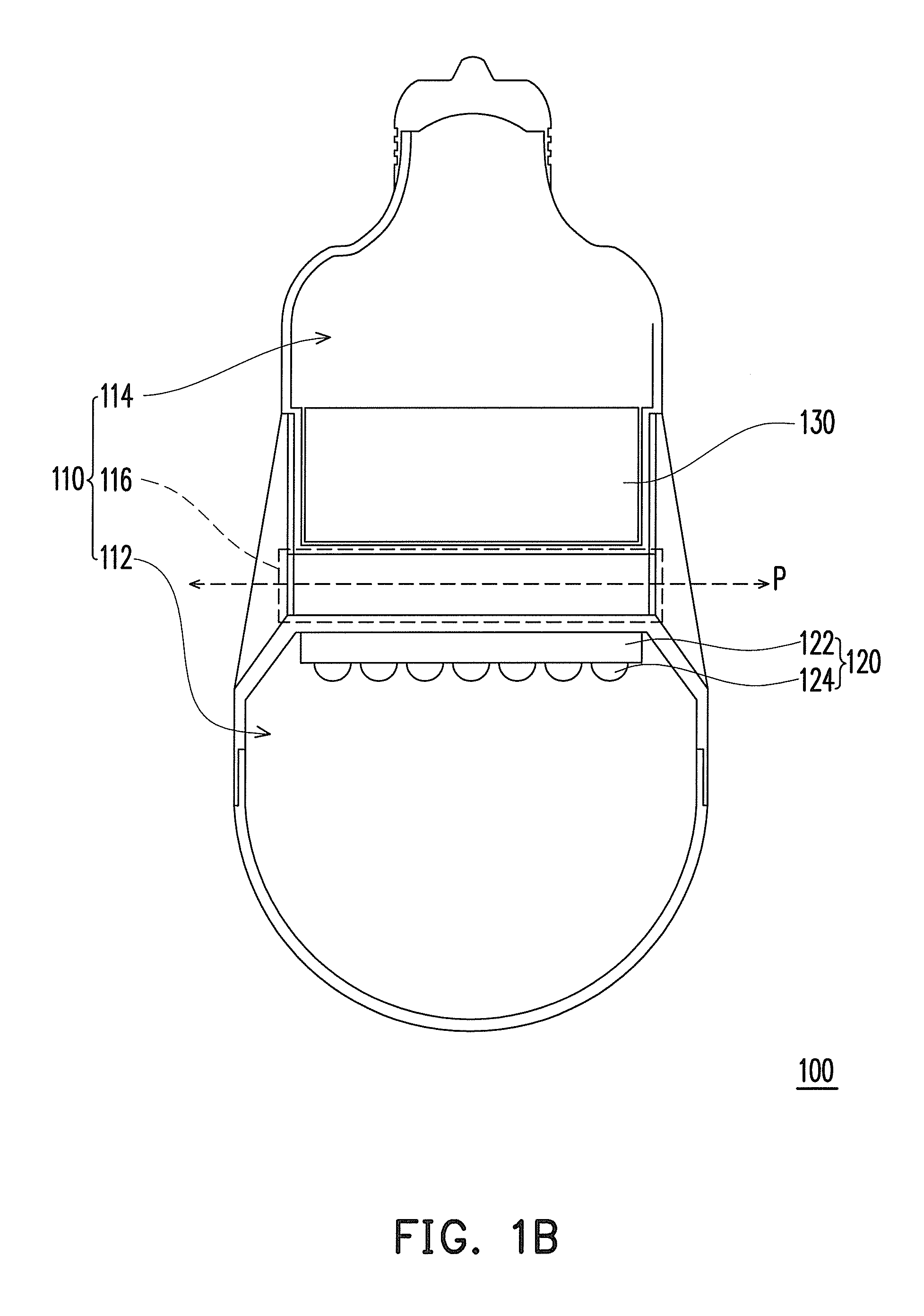
[0029]FIG. 1A is a schematic perspective view of an LED illumination apparatus according to the first embodiment of the invention. FIG. 1B is a schematic cross-sectional view of the LED illumination apparatus in FIG. 1A. Referring to FIG. 1A and FIG. 1B, in this embodiment, an LED illumination apparatus 100 includes a housing 110, an LED light source 120, and a power supply unit 130. The housing 110 has a light source accommodating space 112, a power supply accommodating space 114, and a first thermal isolation channel 116 linked to an atmosphere, wherein the first thermal isolation channel 116 is located between the light source accommodating space 112 and the power supply accommodating space 114. The LED light source 120 and the power supply unit 130 are respectively disposed in the light source accommodating space 112 and the power supply accommodating space 114.

[0030]The housing 110, the LED light source 120, and the power supply unit 130 can have various configurations. The str...

second embodiment

[0035]FIG. 2 is a schematic cross-sectional view of an LED illumination apparatus according to the second embodiment of the invention. With reference to FIG. 2, an LED illumination apparatus 100b of this embodiment is similar to the illumination apparatus of the first embodiment and includes a housing 110, an LED light source 120, and a power supply unit 130. In this embodiment, the housing 110 is a street lamp cover 140b which includes a upper lamp cover 142b, a bottom lamp cover 146b, and a light-transmissive portion 148b.

[0036]More specifically, the upper lamp cover 142b defines the power supply accommodating space 114 for containing the power supply unit 130, wherein the upper lamp cover 142b has a plurality of gas circulation holes 149b. An end of the bottom lamp cover 146b is connected with the other end of the upper lamp cover 142b, wherein the first thermal isolation channel 116 is located between the upper lamp cover 142b and the bottom lamp cover 146b, and the gas circula...

third embodiment

The Third Embodiment

[0040]FIG. 3 is a schematic cross-sectional view of an LED illumination apparatus according to the third embodiment of the invention. Referring to FIG. 3, an LED illumination apparatus 100c of this embodiment is similar to the LED illumination apparatus 100b of the second embodiment. The main difference between the foregoing apparatuses lies in that: the street lamp cover 140b of this embodiment further includes a shielding plate S positioned above the power supply unit 130, wherein the shielding plate S is connected with the upper lamp cover 142b to form a second thermal isolation channel 116′ between the shielding plate S and the upper lamp cover 142b.

[0041]When the LED illumination apparatus 100c is used outdoors, the shielding plate S shields the power supply unit 130 from strong sunlight, which may overheat the power supply unit 130 and cause damage. In addition, the second thermal isolation channel 116′ performs functions similar to the first thermal isola...


PUM


Abstract

A light-emitting diode (LED) illumination apparatus including a housing, an LED light source, and a power supply unit is provided. The housing has a light source accommodating space, a power supply accommodating space and a thermal isolation channel linked to the atmosphere, wherein the thermal isolation channel is located between the light source accommodating space and the power supply accommodating space. The LED light source is disposed in the light source accommodating space and the power supply unit is disposed in the power supply accommodating space. The thermal isolation channel is capable of preventing thermal interference between the LED light source and the power supply unit.

Description

CROSS-REFERENCE TO RELATED APPLICATION[0001]This application claims the priority benefits of U.S. provisional application Ser. No. 61 / 088,356, filed. on Aug. 13, 2008 and of Taiwan patent application serial no. 98125332, filed on Jul. 28, 2009. The entirety of each of the above-mentioned patent applications is hereby incorporated by reference herein and made a part of specification.BACKGROUND OF THE INVENTION[0002]1. Field of the Invention[0003]The invention relates to a light-emitting diode (LED) illumination apparatus and particularly to an LED illumination apparatus having favorable efficiency in heat dissipation.[0004]2. Description of Related Art[0005]A light-emitting diode (LED) is a semiconductor element, and the material for forming a light-emitting chip of an LED mainly includes chemical elements selected from groups III-V, such as gallium phosphide (GaP), gallium arsenide (GaAs), and other compound semiconductors. The light-emitting principle is converting electric energy ...

Claims


Application Information

Patent Timeline
IPC IPC(8): H01J61/52
CPCF21S8/08F21V29/004F21W2131/103F21Y2101/02F21V23/023F21V29/89F21K9/135F21V29/773F21V29/83F21V29/86F21V3/02F21K9/232F21Y2115/10F21V29/763
Inventor TSAI, WEN-KUEI
Owner CHANG WAH ELECTROMATERIALS INC
Why Eureka
Try Eureka