Prosthetic foot

a prosthetic foot and foot technology, applied in the field of shock absorption prosthetic feet, can solve the problems of known energy-transferring designs, bulkiness, complexity, heavy weight, etc., and achieve the effects of promoting good energy-transferring, different mechanical properties, and imparting shock-absorbing flexibility characteristics

Active Publication Date: 2010-02-18
WILLOWWOOD GLOBAL LLC
View PDF36 Cites 91 Cited by
  • Summary
  • Abstract
  • Description
  • Claims
  • Application Information

AI Technical Summary

Benefits of technology

[0010]Preferably, the shank, foot plate and heel plate are comprised of a composite material, such as, e.g., carbon fiber. Such materials are strong while also promoting good energy transfer during heel strike and toe off. The foot plate is preferably radiused in the heel and toe section to make heel strike and toe off as smooth as possible. Various numbers of bumper assemblies may be present, and such assemblies may be distributed in different patterns so as to maintain separation between at least certain components (e.g., plates) of the foot. The bumper assemblies may have different mechanical properties so as to impart shock absorbency and flexibility characteristics most appropriate for a particular amputee. Preferably, the toe and heel bumper assemblies reside at extreme ends of an associated foot. This allows for a prosthetic foot of the present invention to have an increased spring length, thereby allowing for greater plate flex and, consequently, increased shock absorption and energy return characteristics.
[0011]Embodiments of prosthetic foot of the present invention may be adapted for use with various prosthetic leg designs. For example, the shank may have an elongated vertical portion in typical form, whereas the vertical portion may be truncated or eliminated in low-profile or ultra low-profile forms. In any event, a prosthetic foot of the present invention provides an amputee with a versatile, efficient and stable foundation.

Problems solved by technology

However, known energy transferring designs typically suffer from one or more drawbacks including, but not limited to, bulkiness, complexity, heavy weight, excessive stiffness, inefficient energy transfer, and the inability to properly optimize the dynamic characteristics of the foot for a particular amputee (particularly after the foot has already been assembled).

Method used


Image

  • Prosthetic foot
  • Prosthetic foot
  • Prosthetic foot

Examples


Embodiment Construction

)

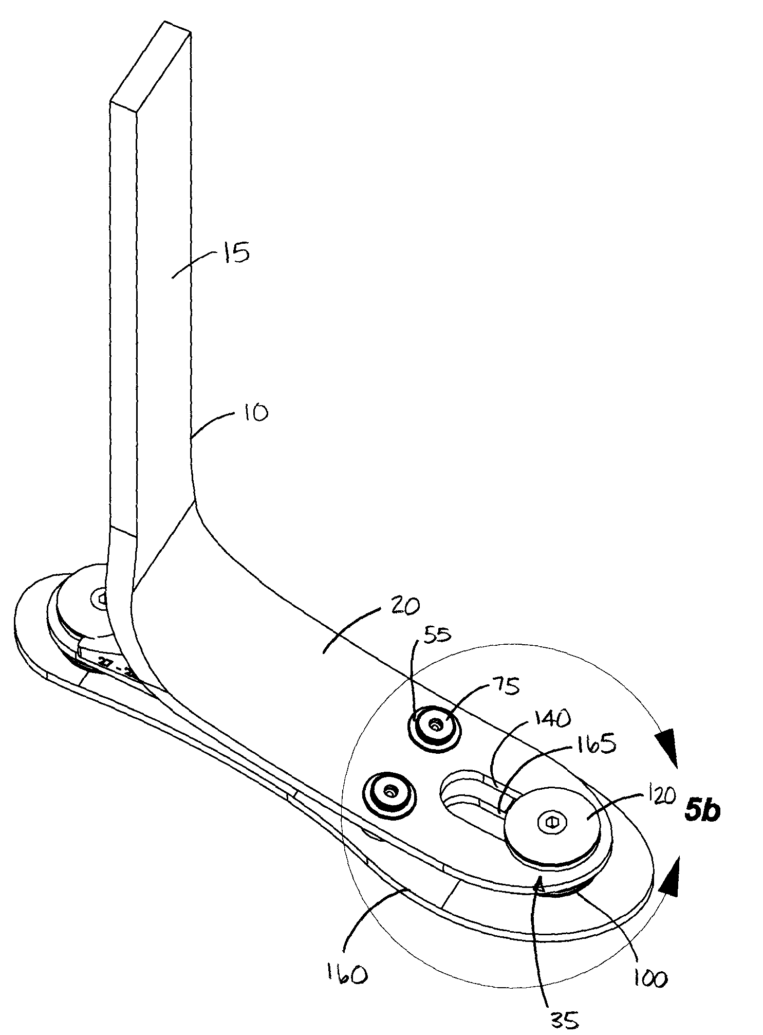
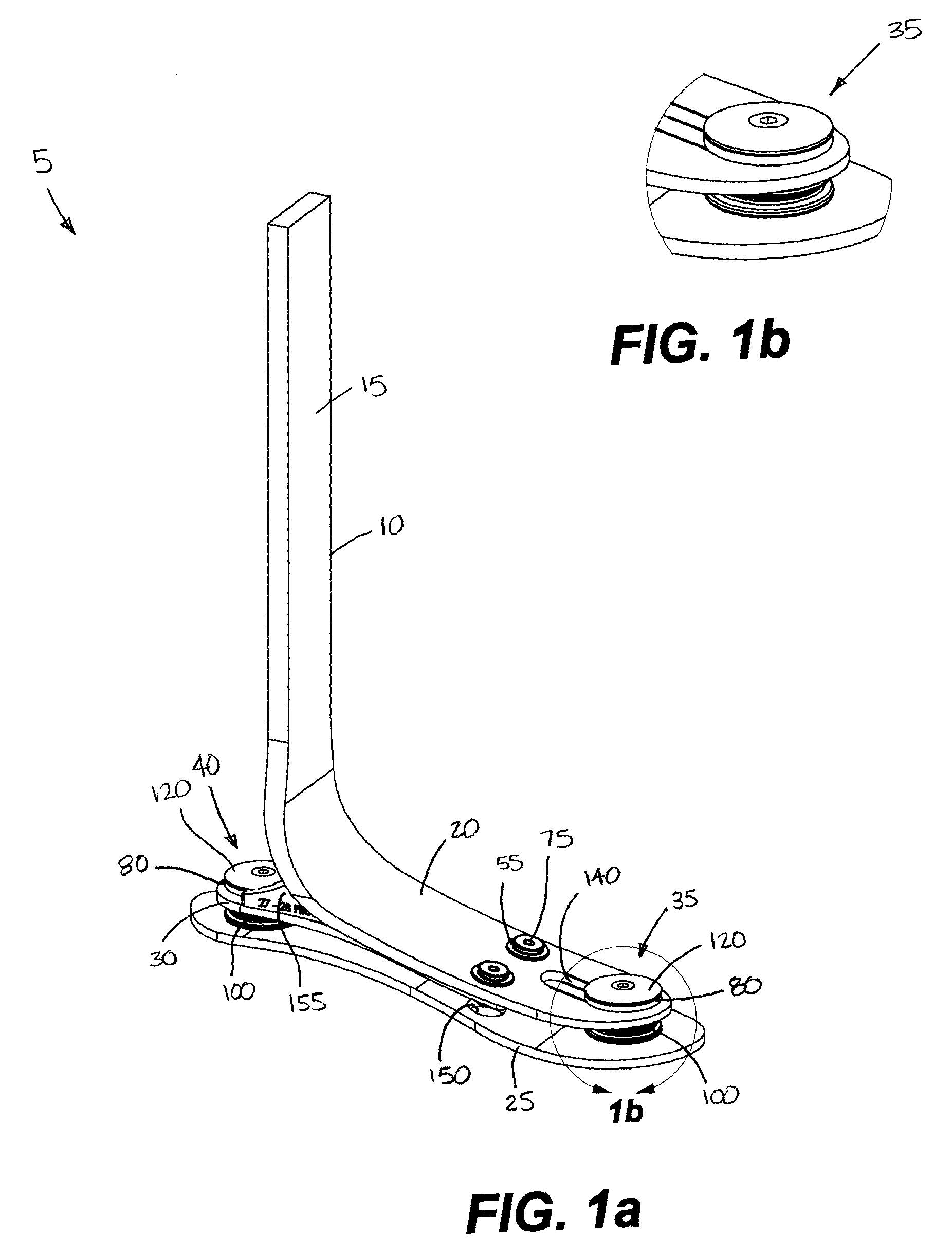
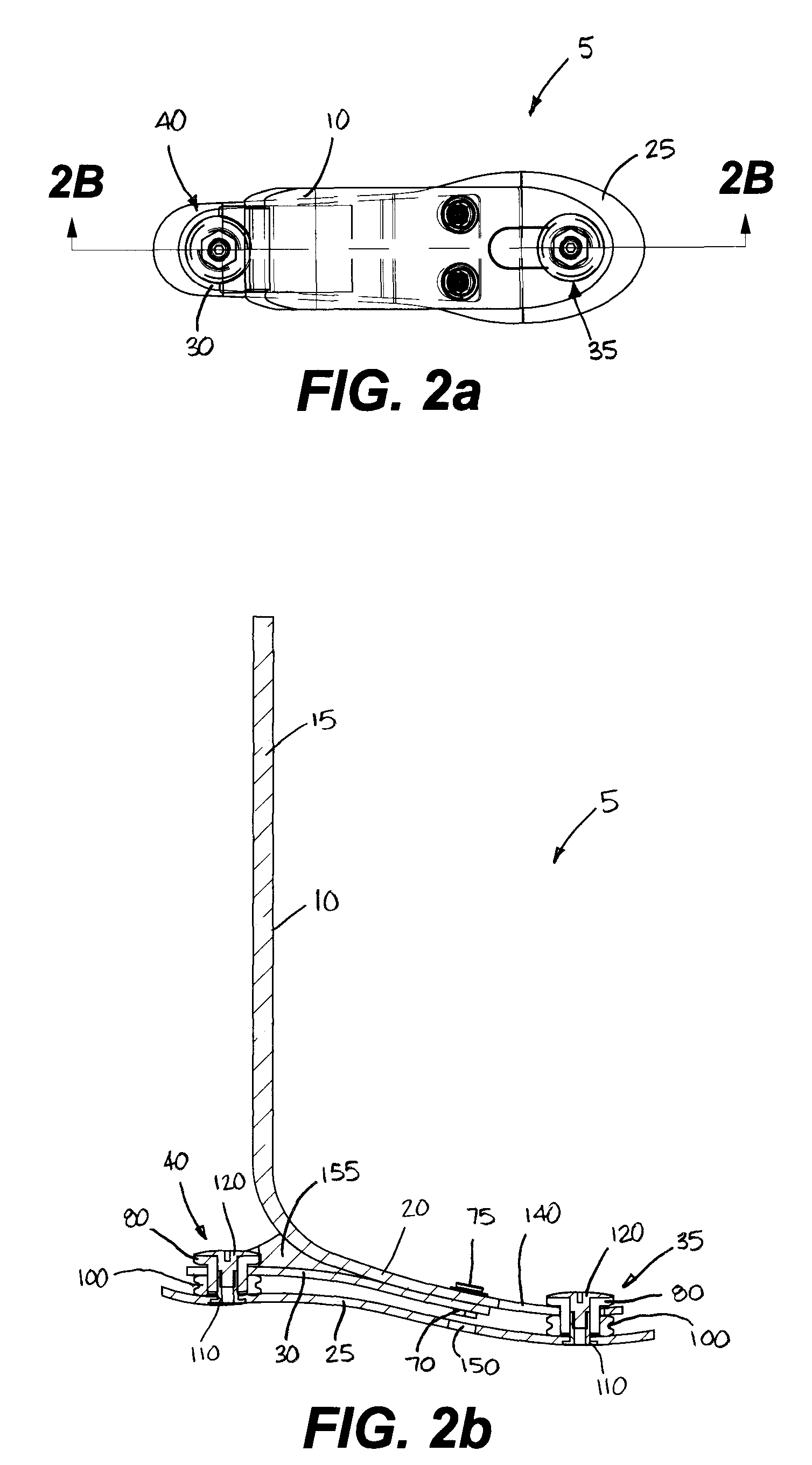
[0031]One exemplary embodiment of a prosthetic foot 5 of the present invention is illustrated in FIGS. 1-3. As shown, the prosthetic foot 5 includes a shank 10, a foot plate 25, and an intermediary heel plate 30. The shank 10 is shown to have an elongated and substantially vertical portion 15 that graduates into a slightly curved foot portion 20. The shank 10 is shaped to control spring rate, so as to accommodate amputees of different weights and activity levels, and also offers dynamic input at both heel strike and toe off. Depending on the materials selected for its manufacturing, the shank 10 may also permit some degree of inversion / eversion movements through twisting in the short direction. The height of the vertical section 15 may be adjusted as needed to accommodate amputees requiring different prosthetic limb lengths.

[0032]The foot plate 25 acts as a base that allows an amputee to maintain balance and stability. Preferably, the foot plate 25 is designed to have some degree o...


PUM


Abstract

A stable shock absorbing prosthetic foot that transfers energy between heel strike and toe-off. A toe plate is separated from one or more other plates by a bumper assembly located at each of the toe end and heel end of the foot. Certain embodiments of the shock absorbing foot of the present invention are designed for use with a prosthetic ankle. A torsion adapter may also be used to attach a prosthetic foot of the present invention to the remainder of a prosthesis.

Description

BACKGROUND OF THE INVENTIVE FIELD[0001]The present invention is directed to shock absorbing prosthetic foot for use by an amputee. More specifically, the present invention is directed to a versatile and configurable shock absorbing prosthetic foot having a number of flexible bumper assemblies that allow the damping and energy transfer characteristics of the foot to be easily adjusted.[0002]It is desirable to produce prosthetic feet having the ability to both absorb energy during a heel strike of each step, and to efficiently transfer the energy to the toe of the foot as the step progresses. Ideally, this energy is released at the moment of toe-off to provide energy for the next step.[0003]During ambulation, the foot initially contacts the ground at the heel. Therefore, particularly during strenuous activities, it is desirable for a prosthetic foot to be capable of absorbing the shock of this heel strike, and to transfer the absorbed energy to the toe portion of the prosthetic foot f...

Claims


Application Information

Patent Timeline
Patent Type & Authority Applications(United States)
IPC IPC(8): A61F2/66
CPCA61F2/66A61F2002/6614A61F2/76A61F2002/30359A61F2002/30395A61F2002/30438A61F2002/30446A61F2002/30472A61F2002/30492A61F2002/30509A61F2002/30512A61F2002/5003A61F2002/5009A61F2002/503A61F2002/5083A61F2002/665A61F2002/6664A61F2002/6678A61F2002/6685A61F2220/0025A61F2220/0033A61F2220/0041A61F2/6607A61F2002/30433A61F2002/30507A61F2002/6621A61F2002/6642A61F2002/6657A61F2002/6671
Inventor DODDROE, JEFFREY L.FLORA, CHARLES R.NOLT, LONNIE L.COLVIN, JAMES M.
Owner WILLOWWOOD GLOBAL LLC
Why Eureka
Try Eureka