Method and apparatus for simulation by discrete element modeling and supporting customisable particle properties

a discrete element and particle technology, applied in the field of simulation systems, can solve the problems of inability to meet the requirements of other simulations, particle temperature may not be relevant for other simulations, and existing systems have limited flexibility for coping, etc., to achieve easy extension, increase flexibility, and widen the scope of use

Active Publication Date: 2010-02-18
ALTAIR ENG LTD
View PDF12 Cites 18 Cited by
  • Summary
  • Abstract
  • Description
  • Claims
  • Application Information

AI Technical Summary

Benefits of technology

[0007]This approach offers increased flexibility, scope and ease-of-use compared with existing systems, and provides a platform which can be readily extended by users with customisable particle properties to cover a wide range of particle simulations for discrete element modeling. The custom properties can be seamlessly integrated into, and subsequently analysed in conjunction with, the existing predefined particle properties.

Problems solved by technology

In fact, the great diversity of applications for discrete element modeling has caused problems due to the need to accommodate a wide range of physical models, each having its own properties and parameters for the individual particles.
Thus it can be difficult and time-consuming for a standard discrete element modeling system to be used if the particle properties and attributes for the desired simulation differ from the default set provided in the standard modeling system.
For example, in some applications, the temperature of the particles plus heat transfer between the particles and their surroundings (and each other) is of significant interest; however, particle temperature may not be relevant for other simulations.
Existing systems have limited flexibility for coping with the proliferation of potential applications for discrete element modeling.

Method used


Image

  • Method and apparatus for simulation by discrete element modeling and supporting customisable particle properties
  • Method and apparatus for simulation by discrete element modeling and supporting customisable particle properties
  • Method and apparatus for simulation by discrete element modeling and supporting customisable particle properties

Examples


Embodiment Construction

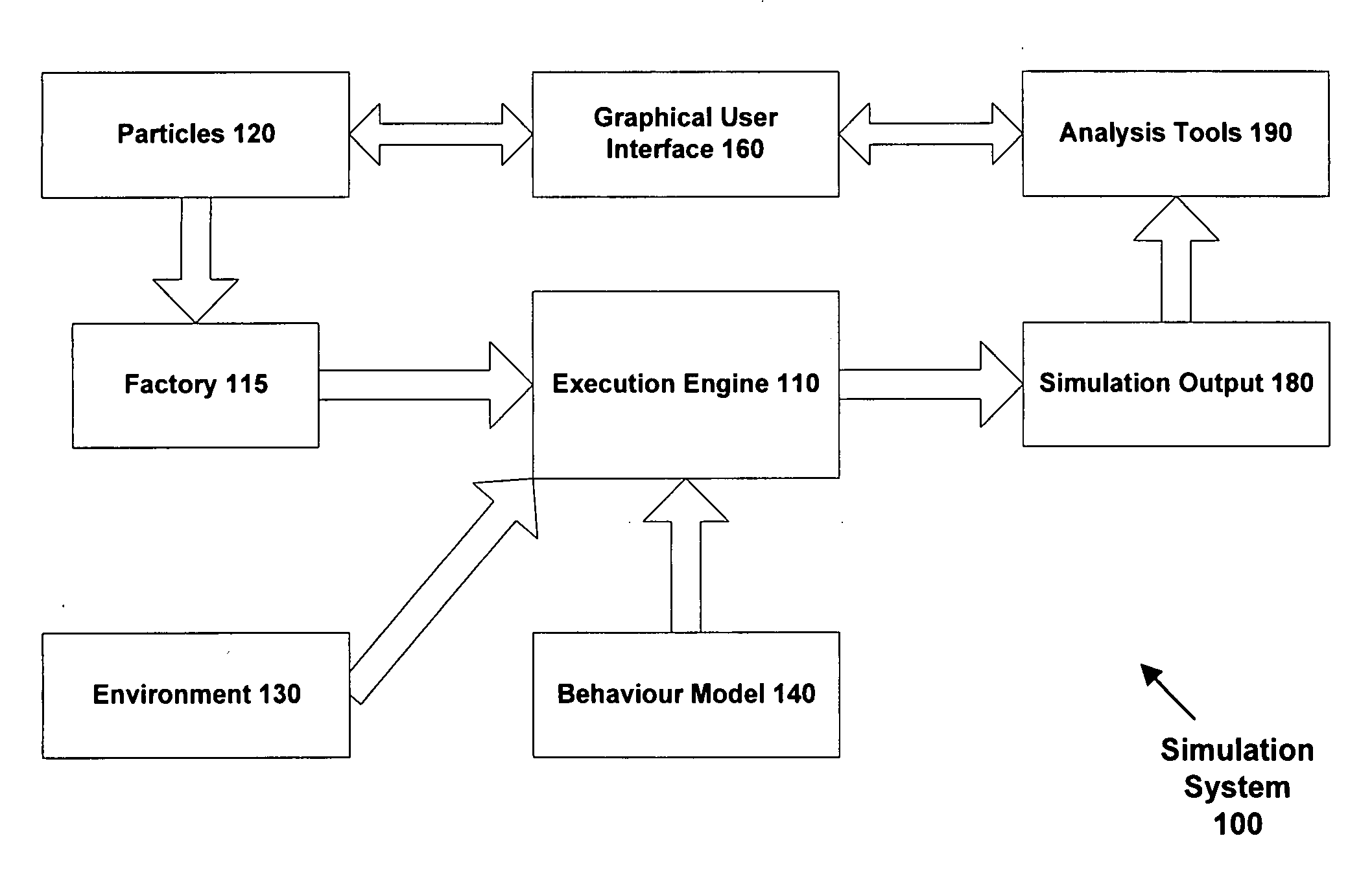
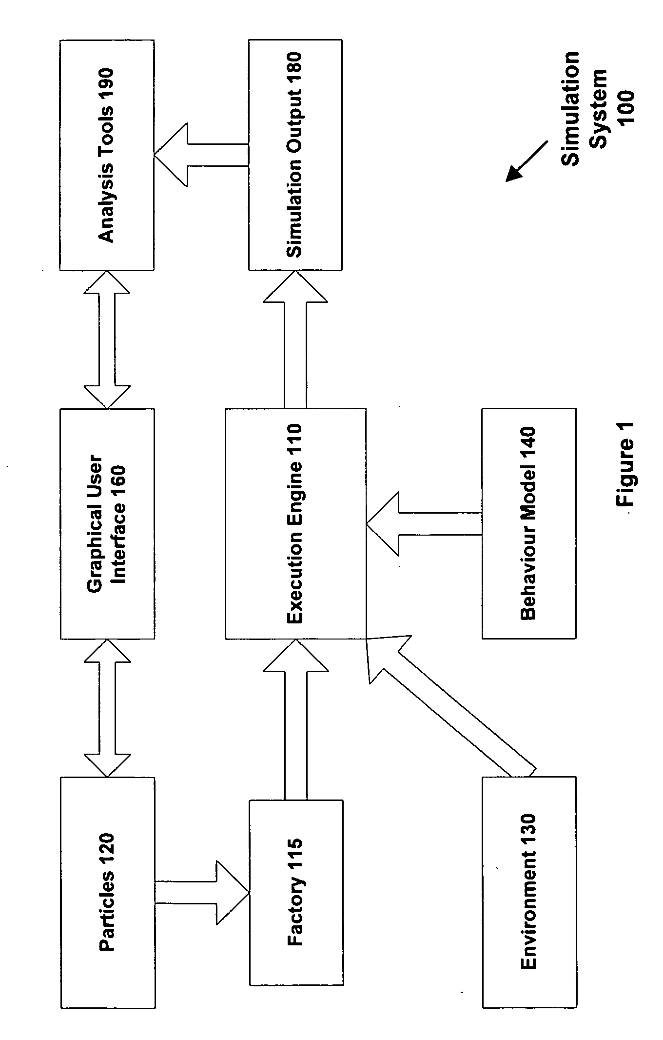
[0017]FIG. 1 is a schematic diagram showing the operation of a simulation system 100 in accordance with one embodiment of the invention. The simulation system is based on an execution engine 110 which takes as input:

[0018](a) a set of particles 120 with properties, such as shape, size, etc. The properties typically specify physical attributes of the particles, as well as parameters for use in the simulation, such as residence time. The system supports multiple different types of particles in a single simulation.

[0019](b) an environment 130 specifying the surroundings of the particles, including boundary conditions and geometry elements. The environment determines the presence of other objects with which the particles may interact and whose behaviour is controlled separately from the particles themselves. The environment may define (for example) the size and shape of a container holding the particles, any objects within the container, plus any operational movement (such as for a conv...


PUM


Abstract

One embodiment of the invention provides a computer-implemented simulation system for discrete element modeling. The system comprises discrete elements corresponding to objects or particles, where each particle has a predefined set of properties. The system further has an interface for receiving at least one behaviour model for applying to the particles, and supports receipt from the at least one model of one or more custom properties for the particles. The system is responsive to receipt of the one or more custom properties to extend the discrete elements to contain both the predefined set of properties and the one or more custom properties for the particles. The system is operable to perform a simulation using discrete element modeling by applying the at least one behaviour model to the particles and to update accordingly values of the predefined and custom properties. The values of the custom particle properties are stored with the default (built-in) particle property values and can be analysed and visualised in the same way as the default property values.

Description

FIELD OF THE INVENTION[0001]The present invention relates to simulation systems, and in particular to simulation systems based on discrete element modeling (DEM).BACKGROUND OF THE INVENTION[0002]Discrete element modeling (also referred to as discrete particle, distinct element, or distinct particle modeling) is used for simulating a wide range of physical, industrial, engineering and / or manufacturing processes and operations. The discrete elements, also referred to as particles, represent objects located in a three-dimensional space that interact dynamically with each other and their surroundings subject to specified physical models or heuristics. The physical interactions are often based on surface contact, although other forces, such as electromagnetic field effects and / or fluid drag, may also be involved. The particles are often defined as being of finite (non-zero) size, but may in some simulations be treated as point objects.[0003]Discrete element modeling allows for the simula...

Claims


Application Information

Patent Timeline
Patent Type & Authority Applications(United States)
IPC IPC(8): G06G7/48
CPCG06F2217/16G06F17/5018G06F30/23G06F2111/10
Inventor MILNE, ANDREW
Owner ALTAIR ENG LTD
Why Eureka
Try Eureka