Co2 refrigerant system with booster circuit

a refrigerant system and booster circuit technology, applied in the field of refrigerant systems, can solve the problems of refrigerant system designers, refrigerant systems utilizing cosub>2/sub>as a refrigerant do not always operate at the efficiency level of traditional refrigerant systems

Inactive Publication Date: 2010-02-25
CARRIER CORP
View PDF16 Cites 38 Cited by
  • Summary
  • Abstract
  • Description
  • Claims
  • Application Information

AI Technical Summary

Benefits of technology

[0004]A separate closed-loop booster circuit is provided in combination with a main refrigerant circuit utilizing CO2 as a refrigerant. The booster circuit provides extra cooling for the high pressure refrigerant, in addition to the cooling provided in the heat rejection heat exchanger of the main CO2 system. The booster circuit may also utilize CO2 as a refrigerant.

Problems solved by technology

However, there are challenges for a refrigerant system designer with regard to utilizing CO2.
Therefore, refrigerant systems utilizing CO2 as a refrigerant do not always operate at the efficiency levels of traditional refrigerant systems.

Method used


Image

  • Co2 refrigerant system with booster circuit
  • Co2 refrigerant system with booster circuit
  • Co2 refrigerant system with booster circuit

Examples


embodiment 44

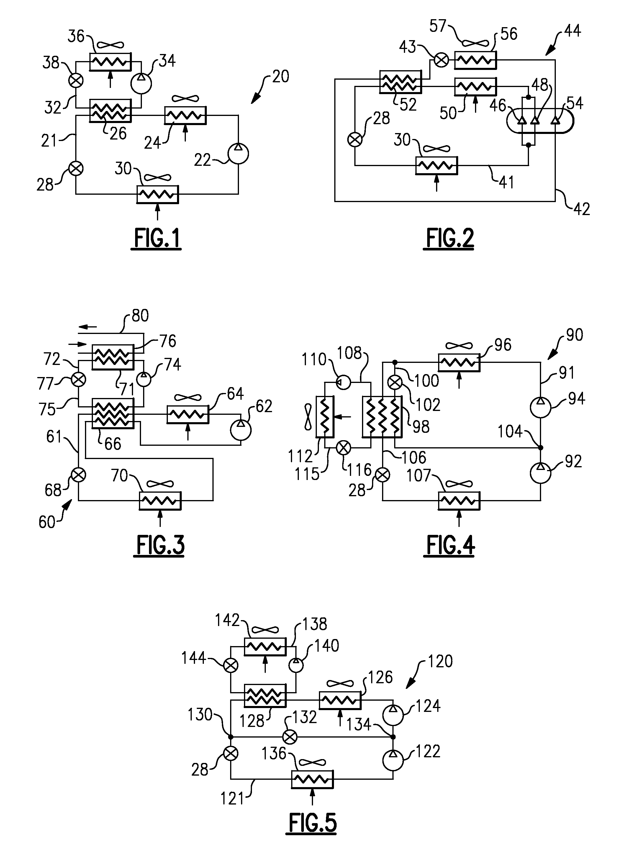
[0021]As shown in FIG. 2, another embodiment 44 provides tandem compressor stages 46 and 48 which circulate refrigerant through a main circuit 41, including a heat rejection heat exchanger 50, a heat exchanger 52, the expansion device 28, and the evaporator 30. A separate compressor stage 54 compresses the refrigerant in a booster circuit 42 and circulates it through a heat rejection heat exchanger 56, the heat exchanger 52, an expansion device 43 and back to the compressor 54. As shown, a fan system 57 may be designed to move air over both heat rejection heat exchangers 50 and 56. In this manner, there is not the requirement of a separate air-moving device for each heat exchanger. Although heat rejection heat exchangers 50 and 56 are shown in a sequential arrangement, with respect to the airflow, they can also be positioned in a parallel configuration.

[0022]The tandem compressors 46 and 48 of the main circuit 41 and the compressor 54 of the booster circuit 42 may all be receiving p...

embodiment 60

[0023]FIG. 3 shows an embodiment 60, wherein the compressor 62 of the main circuit 61 delivers refrigerant sequentially to a heat rejection heat exchanger 64, a heat exchanger 66, an expansion device 68 and an evaporator 70. As shown in FIG. 3, the refrigerant in the main circuit 61 flows from the evaporator 70 back through the heat exchanger 66, before returning to the compressor 62. In this manner, the heat exchanger 66 performs a function similar to a “liquid-to-suction” heat exchanger function (since, in transcritical operation, there may not be any liquid at the exit of the heat rejection heat exchanger 64 of the main circuit 61). This function is assisted and enhanced by a booster circuit 75, since extra cooling is obtained by the main circuit refrigerant entering an expansion device 68. This increase in the cooling capacity would normally be substantially higher then subsequent decrease in the cooling capacity caused by density reduction of the refrigerant vapor entering the ...


PUM


Abstract

A refrigerant system, which utilizes CO2 as a refrigerant, includes a main closed-loop refrigerant circuit and a booster closed-loop refrigerant circuit. A heat accepting heat exchanger, which provides extra cooling for the refrigerant circulating through the main circuit, and thus improves refrigerant system performance, also serves as a shared component coupling the two circuits through heat transfer interaction. Various schematics and configurations for the booster circuit, which may be combined with other performance enhancement features, are disclosed. Additional benefits for economizer function, “liquid-to-suction” heat exchanger, intercooling and liquid injection are also presented. The booster circuit may also contain CO2 refrigerant.

Description

BACKGROUND OF THE INVENTION[0001]This application relates to refrigerant systems which utilize CO2 refrigerant and are provided with a booster circuit to enhance operational performance.[0002]Refrigerant systems are known in the HVAC&R (heating, ventilation, air conditioning and refrigeration) art, and operate to compress and circulate a refrigerant throughout a closed-loop refrigerant circuit, connecting a plurality of components, to condition a secondary fluid to be delivered to a climate-controlled space. In a basic refrigerant system, refrigerant is compressed in a compressor from a lower to a higher pressure and delivered to a downstream heat rejection heat exchanger, which is a so-called gas cooler, in transcritical applications, or a so-called condenser, in subcritical applications. From the heat rejection heat exchanger, where heat is typically transferred from the refrigerant to ambient environment, a high-pressure refrigerant flows to an expansion device where it is expand...

Claims


Application Information

Patent Timeline
Patent Type & Authority Applications(United States)
IPC IPC(8): F25B1/00F25B6/02
CPCF25B1/10F25B7/00F25B40/00F25B40/02F28D2021/0068F25B2400/074F25B2400/13F28F9/0234F25B2309/061
Inventor TARAS, MICHAEL F.LIFSON, ALEXANDER
Owner CARRIER CORP
Why Eureka
Try Eureka