Circular-Shaped Linear Synchronous Motor, Electromagnetic Suspension and Motor-Driven Steering Device Using the Same

a technology of electromagnetic suspension and linear synchronous motor, which is applied in the direction of motor/generator/converter stopper, electronic commutator, dynamo-electric converter control, etc., can solve the problems of linear motors that cannot exhibit high-damping performance, linear motors that cannot achieve high-damping performance, and reduced per-volume thrust and damping performance. , to achieve the effect of high-damping and high-thrust performan

Inactive Publication Date: 2010-02-25
HITACHI AUTOMOTIVE SYST LTD
View PDF9 Cites 20 Cited by
  • Summary
  • Abstract
  • Description
  • Claims
  • Application Information

AI Technical Summary

Benefits of technology

[0014]The configuration as described above allows acquisition of the high-damping and high-thrust performance.
[0015]According to the present invention, it becomes possible to permit the linear motor and this-motor-used electromagnetic suspension to exhibit the high-damping and high-thrust performance.

Problems solved by technology

As a result of this relationship, saturation of magnetic paths of the permanent magnets imposes a limitation on the thrust which the linear motor is capable of exhibiting.
Accordingly, there has existed a problem that the linear motor is incapable of exhibiting the high-damping performance.
As a result, there has existed a problem that the per-volume thrust and damping performances are reduced.

Method used


Image

  • Circular-Shaped Linear Synchronous Motor, Electromagnetic Suspension and Motor-Driven Steering Device Using the Same
  • Circular-Shaped Linear Synchronous Motor, Electromagnetic Suspension and Motor-Driven Steering Device Using the Same
  • Circular-Shaped Linear Synchronous Motor, Electromagnetic Suspension and Motor-Driven Steering Device Using the Same

Examples


first embodiment

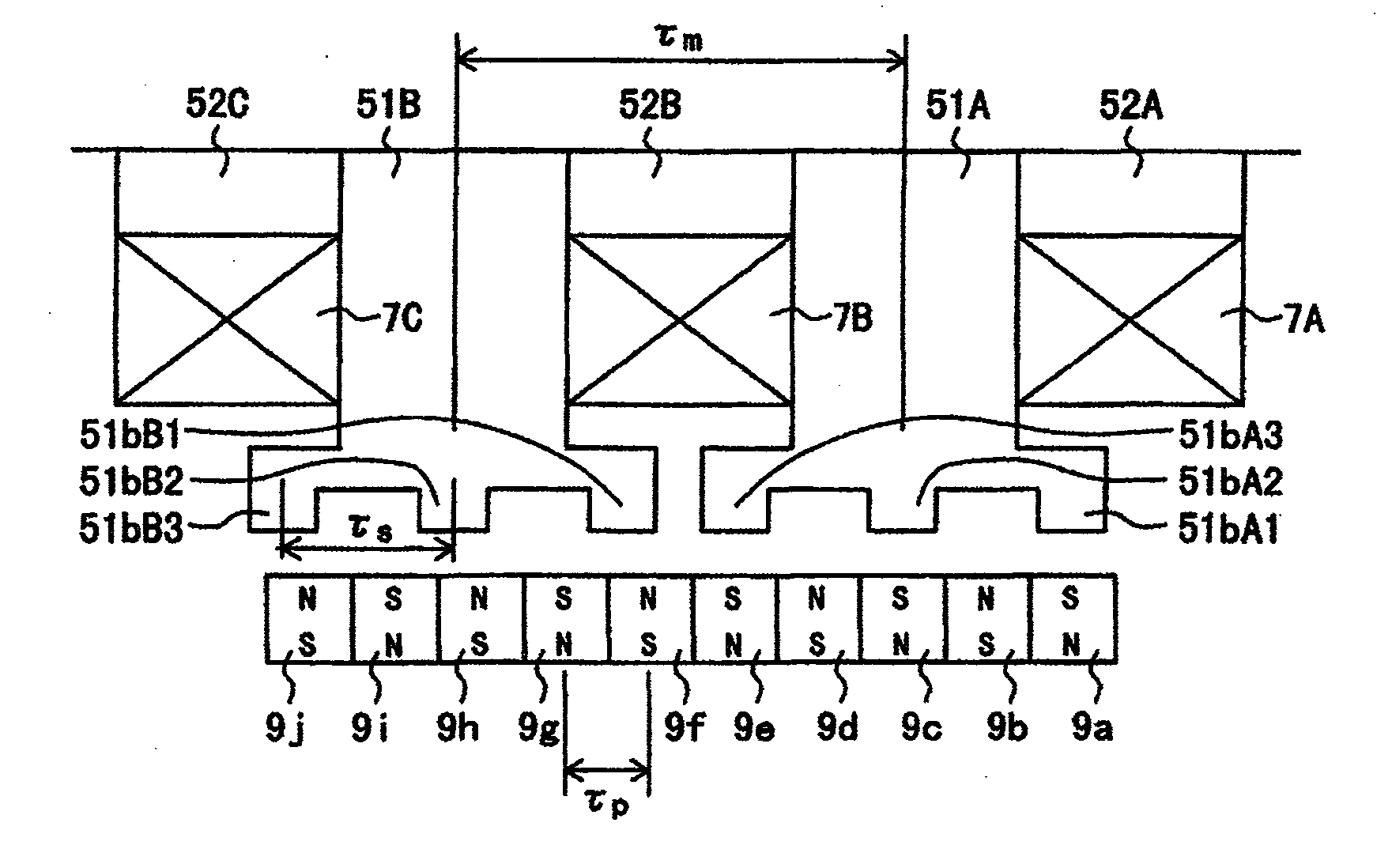
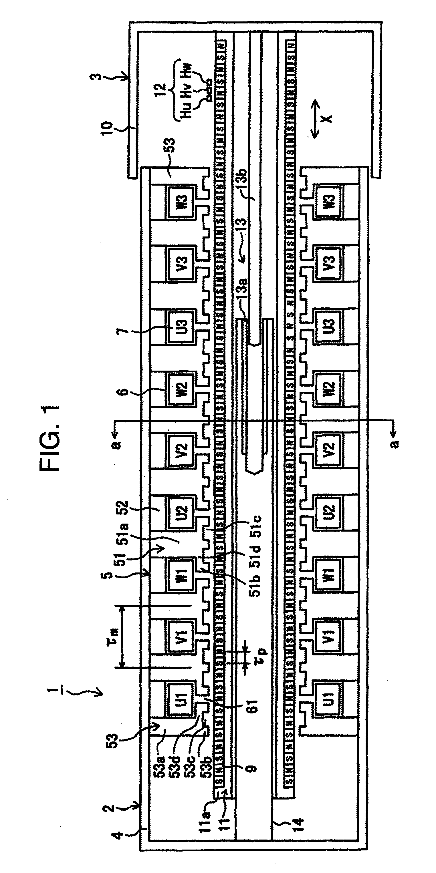
[0038]Hereinafter, referring to FIG. 1 to FIG. 13, the explanation will be given below concerning the configuration of a cylindrical linear motor according to the present invention.

[0039]First, referring to FIG. 1 and FIG. 2, the explanation will be given below regarding the entire configuration of the cylindrical linear motor according to the present embodiment.

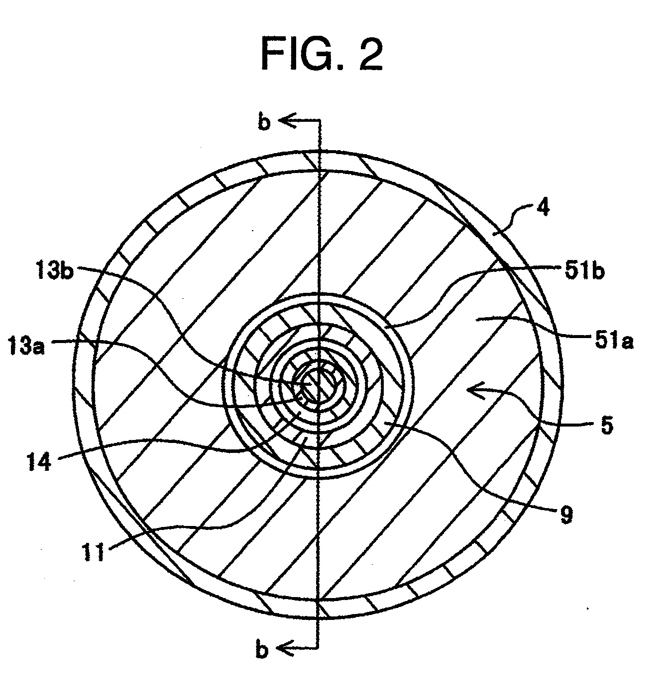
[0040]FIG. 1 is a transverse cross-sectional diagram for illustrating the configuration of the cylindrical linear motor according to the first embodiment of the present invention. FIG. 2 is an a-a cross-sectional diagram of FIG. 1. Also, FIG. 1 is a b-b cross-sectional diagram of FIG. 2.

[0041]As illustrated in FIG. 1, the permanent-magnet type three-phase cylindrical linear motor 1 according to the present embodiment includes a cylinder-shaped stator 2, and a cylinder-shaped slider 3 which is held in a slidably movable manner inside the stator 2.

[0042]The stator 2 includes a stator case 4, a stator core 5, three-phase stator...

second embodiment

[0152]Next, referring to FIG. 14, the explanation will be given below concerning the entire configuration of a cylindrical linear motor according to the present invention.

[0153]FIG. 14 is a transverse cross-sectional diagram for illustrating the configuration of the cylindrical linear motor according to the second embodiment of the present invention. Incidentally, the same reference numerals as the ones in FIG. 1 denote the same configuration components.

[0154]In the present embodiment, design configuration of auxiliary poles 53A differs from the one illustrated in FIG. 1. Namely, in addition to the auxiliary-pole small poles 53b which configure the magnetic path of the permanent magnets 9, and the auxiliary-pole small pole slits 53c which block the magnetic flux of the adjacent permanent magnets, each of the auxiliary poles 53A further includes a notch portion 53e of the auxiliary pole. This notch portion 53e is provided on the opposite sides to the sides on which the auxiliary pole...

third embodiment

[0160]Next, referring to FIG. 15 to FIG. 20, the explanation will be given below concerning the entire configuration of a cylindrical linear motor according to the present invention.

[0161]First, referring to FIG. 15, the explanation will be given below concerning the entire configuration of the cylindrical linear motor according to the third embodiment of the present invention.

[0162]FIG. 15 is a transverse cross-sectional diagram for illustrating the configuration of the cylindrical linear motor according to the third embodiment of the present invention. Incidentally, the same reference numerals as the ones in FIG. 1 denote the same configuration components.

[0163]In the present embodiment, the main feature lies in the following point: The deployment of the stator 2 and the slider 3 in the inner and outer circumferences is made reverse with respect to the deployment illustrated in FIG. 1.

[0164]The principle of the electromagnetic thrust, which exerts between the stator 2 and the slid...


PUM


Abstract

Disclosed are a high-damping and high-thrust cylindrical linear motor and a motor-driven power steering device. A stator includes three-phase stator and a stator core. A slider includes a slider core and permanent magnets. The stator core includes stator-core salient poles, two auxiliary poles and yoke units with a small poles on its surface of the side of the slider, the auxiliary poles being deployed at both ends of the stator-core salient poles, the yoke units configuring a magnetic circuit in cooperation with the stator core and the auxiliary poles. The magnetic circuit is shared among the three phases. Polarities of magnets of the slider become an identical polarity, each of the plurality of permanent magnets being positioned at a position which is opposed to each of the plurality of small poles included in one stator-core salient pole out of the plurality of stator-core salient poles.

Description

BACKGROUND OF THE INVENTION[0001]1. Field of the Invention[0002]The present invention relates to a cylindrical linear motor, or a circular-shaped linear synchronous motor, an electromagnetic suspension and a motor-driven power steering device using the same motor.[0003]2. Description of the Related Art[0004]Consideration is now given to an attempt to suppress fluctuations of vehicles such as Shinkansen-train or automobile by inverter-using a permanent-magnet type three-phase cylindrical linear motor. In this case, even when the inverter has failed, a hydraulic-pressure damper to be adjacently provided with the cylindrical linear motor can be eliminated, or can be made smaller. This configuration change in the hydraulic-pressure damper is made possible if a large damping force can be ensured by short-circuiting terminals among the three phases of the cylindrical linear motor. As a result of this change, it becomes possible to configure the entire electromagnetic suspension using the ...

Claims


Application Information

Patent Timeline
Patent Type & Authority Applications(United States)
IPC IPC(8): B62D5/04H02K41/03H02P6/14B60G11/00B60G17/00B61F5/12
CPCB60G17/0157B60G2202/422H02K41/03B62D5/04B62D5/0427B61F5/245
Inventor TAJIMA, FUMIOKITAMURA, MASASHIAKAMI, YUSUKEUTSUMI, NORIYUKILEE, TOMOYUKI
Owner HITACHI AUTOMOTIVE SYST LTD
Why Eureka
Try Eureka