Substrate treatment apparatus and substrate treatment method

Inactive Publication Date: 2010-02-25
KK TOSHIBA
View PDF5 Cites 4 Cited by
  • Summary
  • Abstract
  • Description
  • Claims
  • Application Information

AI Technical Summary

Benefits of technology

[0022]in a state where a first liquid flows between the first chamber and a second chamber disposed above or below the first chamber and having higher pressure resistance than the first chamber, moving the subst

Problems solved by technology

For example, in a very fine structure having a line width of twenty-some nm or less, a problem is becoming apparent such that when a substrate is dried, patterns collapse due to surface tension of pure water, a chemical, or the like.
In the conventional art, however, when the aspect ratio of the pattern increases (for example, when the aspect ratio is 15 or higher), it is difficult to suppress collapse of the patterns.
In the substrate treatment apparatus, however, for example, in principle, a water-shedding wafer re

Method used


Image

  • Substrate treatment apparatus and substrate treatment method
  • Substrate treatment apparatus and substrate treatment method
  • Substrate treatment apparatus and substrate treatment method

Examples


Example

First Embodiment

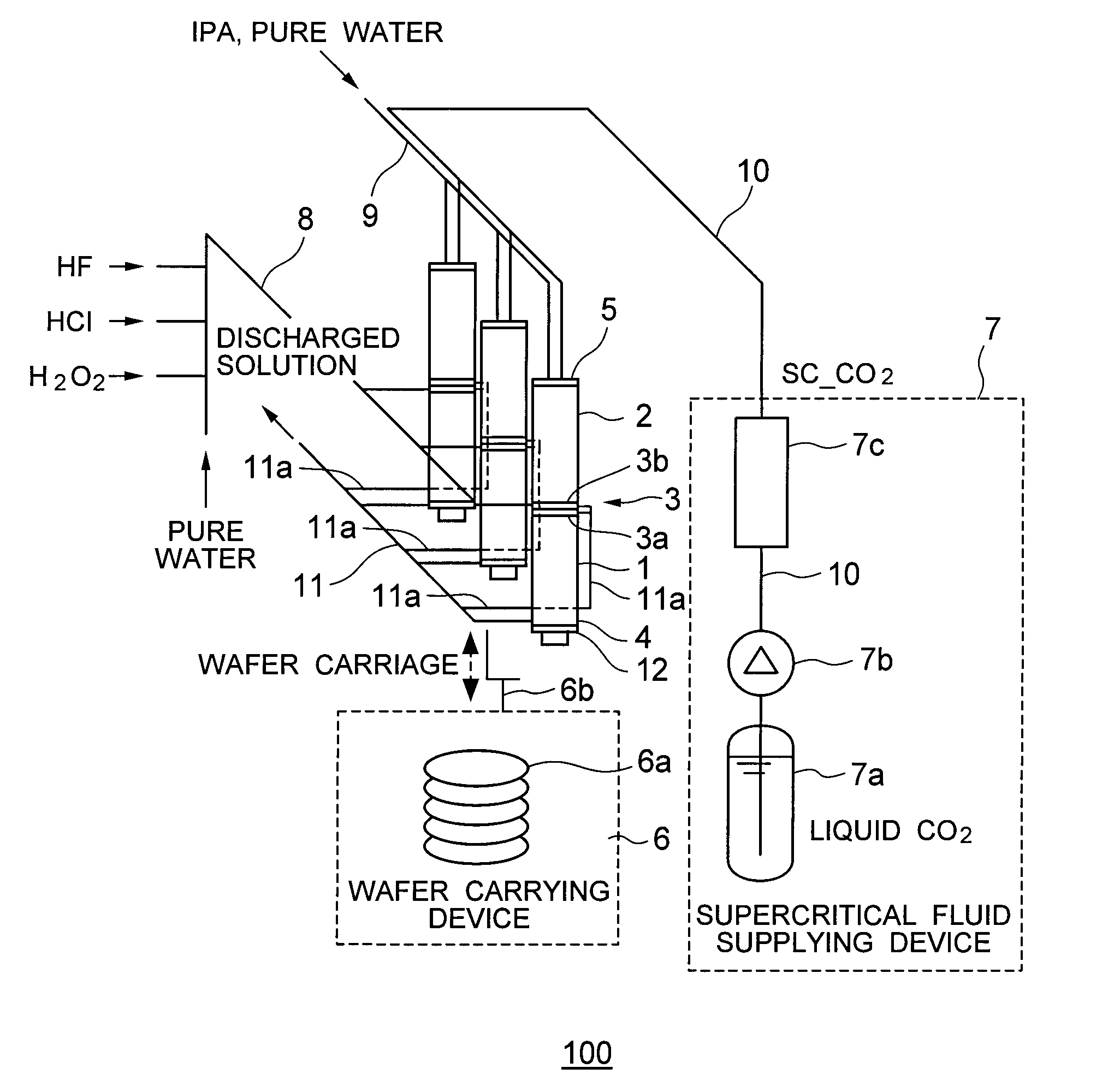
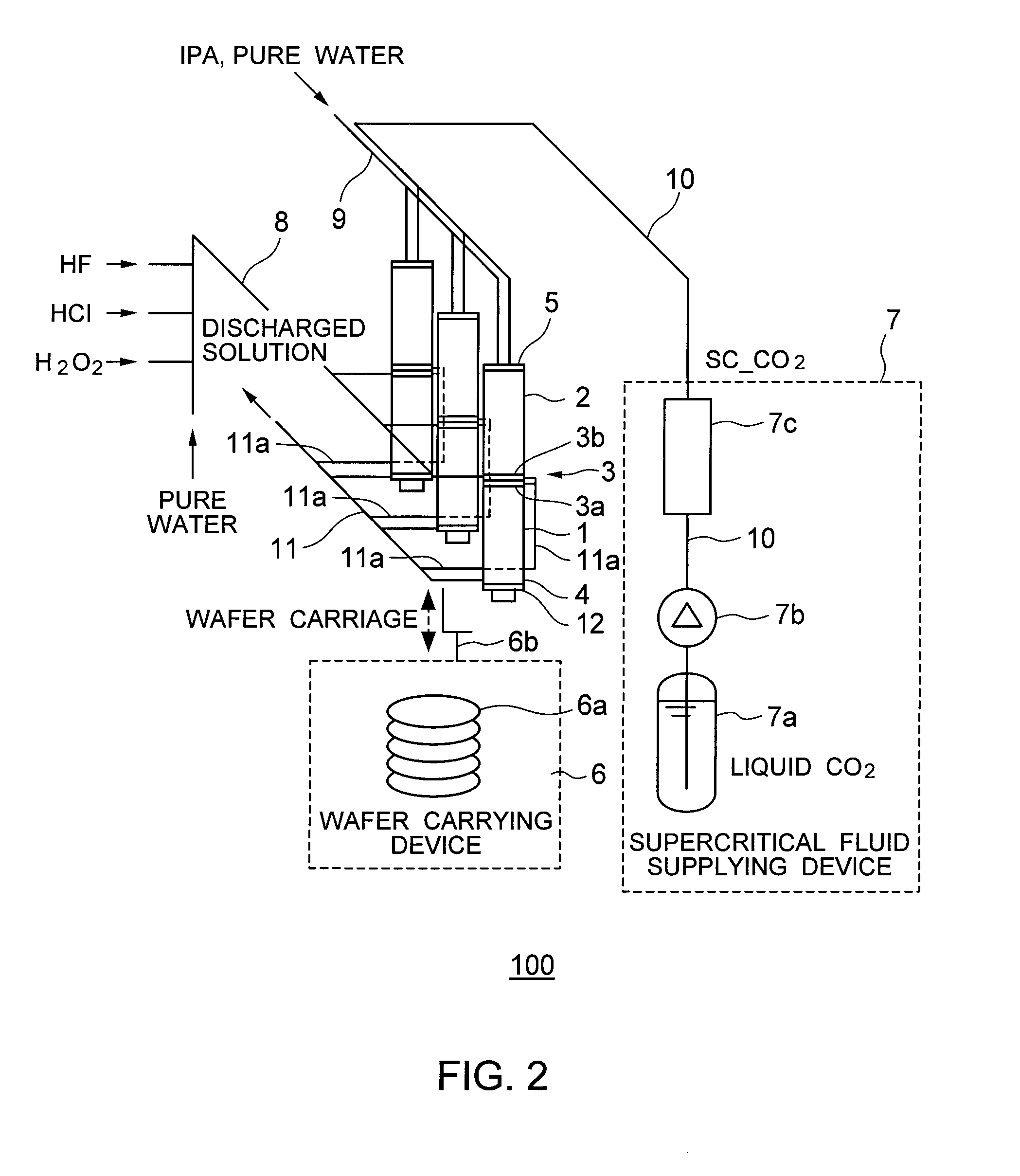
[0053]FIG. 2 is a diagram showing an example of the configuration of a substrate treatment apparatus 100 in a first embodiment as an aspect of the present invention. FIGS. 3 to 5 are diagrams showing an example of operation of opening / closing a gate unit 3 in the substrate treatment apparatus 100 shown in FIG. 2.

[0054]As shown in FIG. 2, the substrate treatment apparatus 100 has a first chamber 1, a second chamber 2, the gate unit 3, connection units 4 and 5, a wafer carrying device 6, a supercritical fluid supplying device 7, a cleaning-solution pipe 8, a replacement-solution pipe 9, a pipe 10, drainage pipes 11 and 11a, and an ultrasonic generator 12.

[0055]The substrate treatment apparatus 100 performs cleaning process, rinsing process, and drying process on a wafer 6a. On the wafer 6a (for example, a substrate such as a semiconductor substrate or a glass substrate), a plurality of patterns are formed adjacently.

[0056]The first chamber 1 has resistance to a chemica...

Example

Second Embodiment

[0104]In the foregoing first embodiment, an example of the configuration for supercritically drying a wafer has been described.

[0105]A supercritical fluid used for the supercritical drying has viscosity lower than that of a gas and has a higher power of carrying a material (for example, a particle having a diameter of about 20 nm). It is consequently difficult to sufficiently purge (clean) the material existing in a pipe for supplying a supercritical fluid by a gas in a manner similar to that in a conventional gas pipe.

[0106]On the other hand, a liquid has viscosity higher than that of a gas and a supercritical fluid and has a high material carrying force. In a second embodiment, an example of a configuration for purging (cleaning) a pipe for supplying the supercritical fluid by a liquid will be proposed. The basic configuration for supercritically drying a wafer is similar to that of the first embodiment.

[0107]FIG. 13 is a diagram showing an example of the configur...


PUM

PropertyMeasurementUnit
Electrical resistanceaaaaaaaaaa
Vapor pressureaaaaaaaaaa

Abstract

A substrate treatment apparatus for treating a substrate on which a plurality of patterns are formed adjacently, has a first chamber which has resistance to a chemical and cleans the substrate with the chemical; a second chamber which is disposed above or below the first chamber, has higher pressure resistance than the first chamber, and supercritically dries the substrate; and a gate unit which is provided between the first and second chambers and can be opened/closed.

Description

CROSS-REFERENCE TO RELATED APPLICATIONS[0001]This application is based upon and claims the benefit of priority from the prior Japanese Patent Application No. 2008-214583, filed on Aug. 22, 2008, and No. 2009-135093, filed on Jun. 4, 2009, the entire contents of which are incorporated herein by reference.BACKGROUND OF THE INVENTION[0002]1. Field of the Invention[0003]The present invention relates to a substrate treatment apparatus and a substrate treatment method for treating a substrate such as a semiconductor substrate or a glass substrate with a chemical.[0004]2. Background Art[0005]In recent years, semiconductor devices are being miniaturized. For example, in a very fine structure having a line width of twenty-some nm or less, a problem is becoming apparent such that when a substrate is dried, patterns collapse due to surface tension of pure water, a chemical, or the like.[0006]In a conventional art, for example, a state where the surface of a substrate is wet with pure water is ...

Claims


Application Information

Patent Timeline
IPC IPC(8): C03C15/00
CPCC03C15/00H01L21/67126H01L21/67028H01L21/302
Inventor TOMITA, HIROSHIJI, LINANOKUCHI, HISASHIKOIDE, TATSUHIKOIIMORI, HIROYASUHAYASHI, HIDEKAZU
Owner KK TOSHIBA
Why Eureka
Try Eureka