

Projector and control method of projector
- Summary
- Abstract
- Description
- Claims
- Application Information
AI Technical Summary
Benefits of technology
Problems solved by technology
Method used
Image

Examples
first embodiment
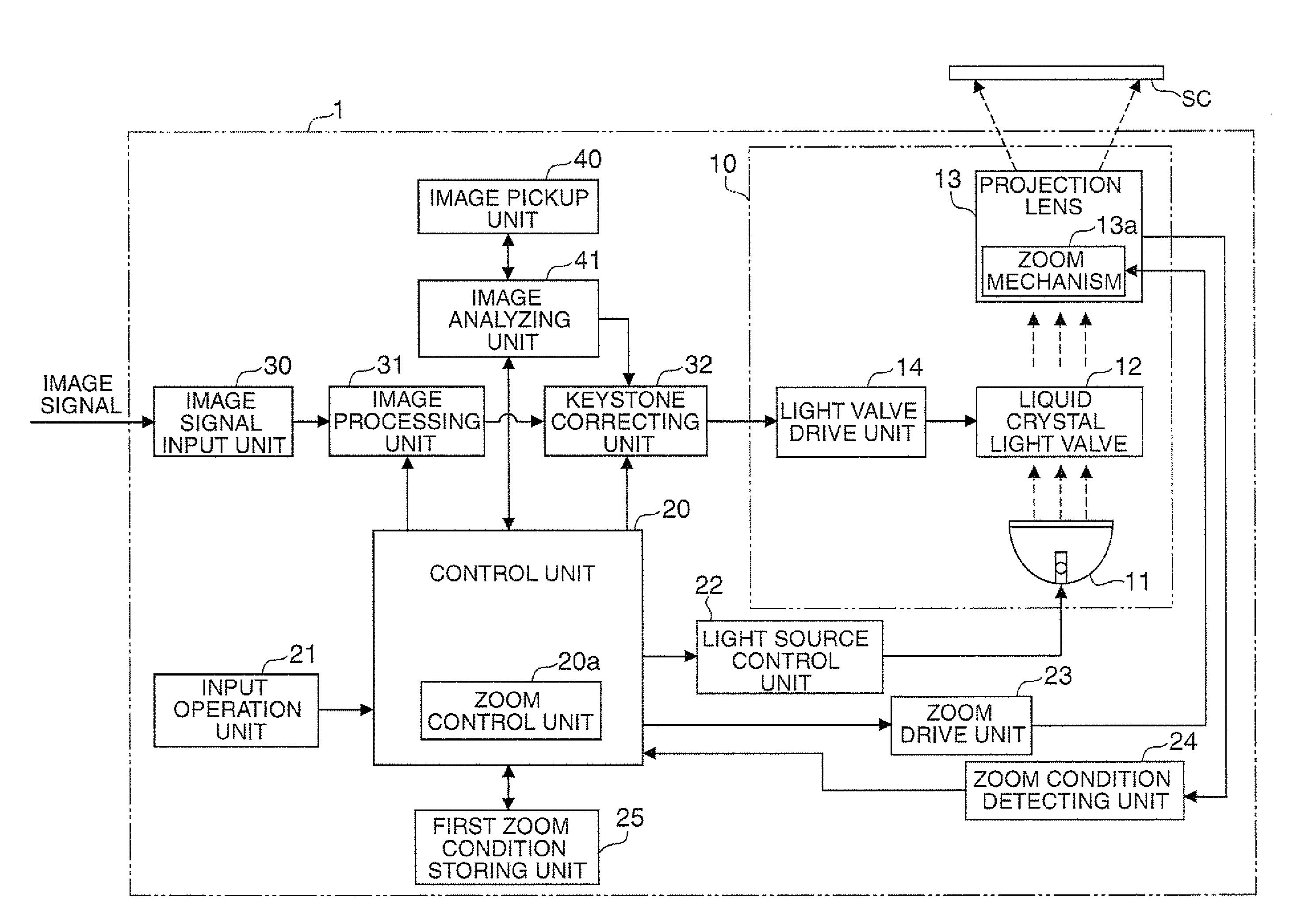
[0034]FIG. 1 is a block diagram showing a general structure of a projector 1 according to a first embodiment. The internal structure of the projector 1 is now discussed with reference to FIG. 1.
[0035]The projector 1 includes an image projecting unit 10, a control unit 20, an input operation unit 21, a light source control unit 22, a zoom drive unit 23, a zoom condition detecting unit 24, a first zoom condition storing unit 25, an image signal input unit 30, an image processing unit 31, a keystone correcting unit 32, an image pickup unit 40, an image analyzing unit 41, and other components. The control unit 20 also functions as an operation signal receiving unit. FIG. 1 shows a screen SC outside the projector 1.
[0036]The image projecting unit 10 has a light source 11 constituted by a discharge type light source such as extra-high pressure mercury lamp and metal halide lamp or a solid light source such as LED (light emitting diode), a liquid crystal light valve 12 as a light modulatio...
second embodiment
[0078]A second embodiment of the invention is now discussed.
[0079]A projector 2 according to the second embodiment has a structure similar to that of the projector 1 in the first embodiment except for the timing for driving the zoom drive unit 23 to set to the first zoom condition. In the first embodiment, the first zoom condition is set when the projector 1 is turned on. According to this embodiment, however, the first zoom condition is set not when the projector 2 is turned on but when the projector 2 is turned off. The automatic zoom control process (zoom control keystone correction process) performed in this embodiment is similar to that in the first embodiment.
[0080]The operation performed when the projector 2 is turned off is now discussed. FIG. 6 is a flowchart showing the process performed when the projector 2 is turned off.
[0081]When a power OFF operation signal of the projector 2 is inputted by press of the power source key of the input operation unit 21, the control unit ...
third embodiment
[0088]A third embodiment of the invention is hereinafter described.
[0089]A projector 3 according to the third embodiment has a zoom amount storing unit 26 in place of the first zoom condition storing unit 25 of the first embodiment. Moreover, the process performed by the zoom control unit 20a is different. Other parts are similar to those in the first embodiment. The automatic zoom control process (zoom control keystone correction process) is also similar to that in the first embodiment.
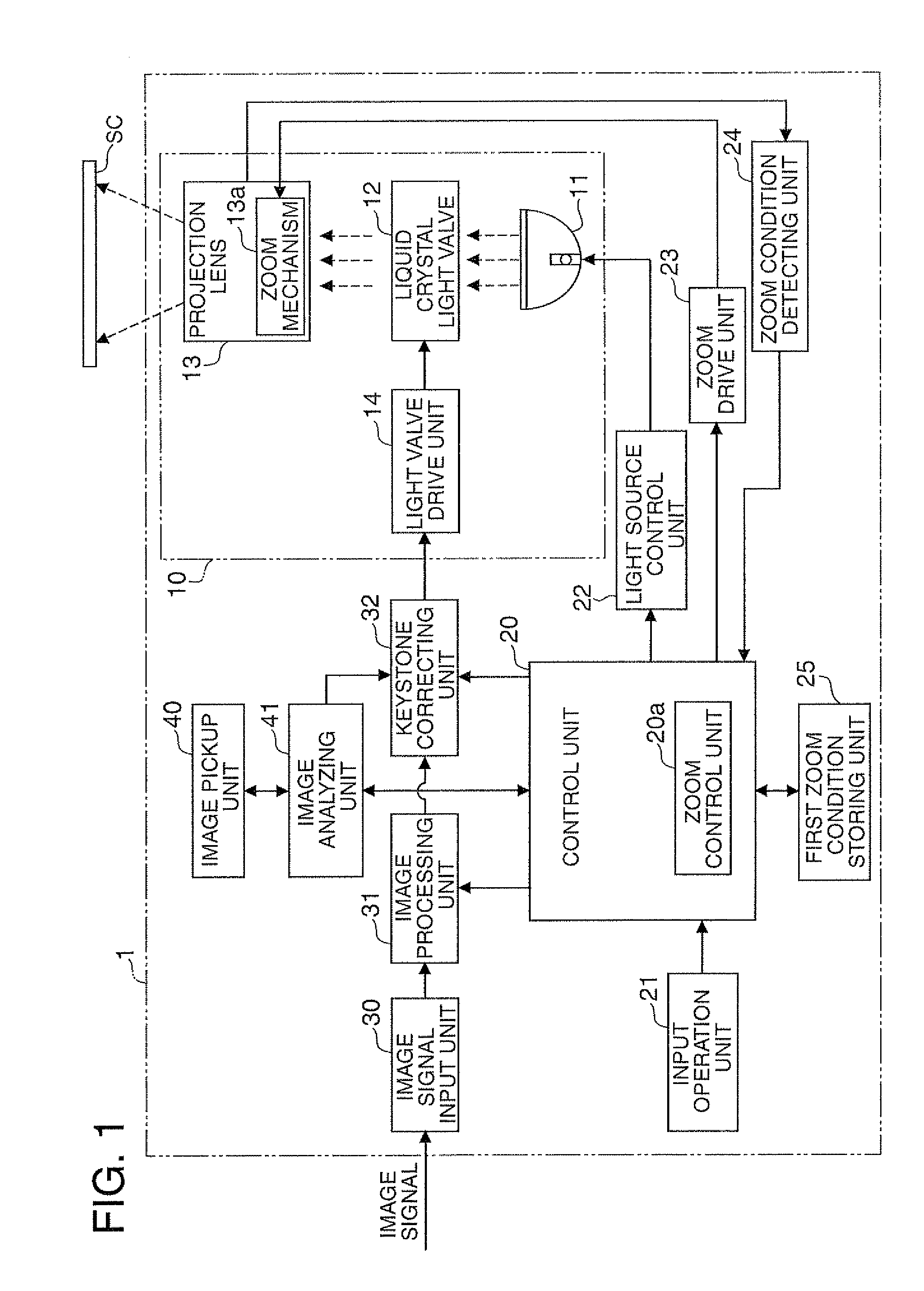
[0090]FIG. 7 is a block diagram showing the general structure of the projector 3 according to the third embodiment. The difference in the internal structure between the projector 3 and the projector 1 is now discussed with reference to FIG. 7.
[0091]The zoom amount storing unit 26 has non-volatile memory to store the minimum and the maximum of the zoom amount provided by the zoom drive unit 23 in response to the input operation by the user. The zoom amount storing unit 26 also stores the minimum value...
PUM
 Abstract
Description
Claims
Application Information