Image pickup lens, image pickup apparatus and mobile terminal

Inactive Publication Date: 2010-02-25
KONICA MINOLTA OPTO
View PDF5 Cites 47 Cited by
  • Summary
  • Abstract
  • Description
  • Claims
  • Application Information

AI Technical Summary

Benefits of technology

[0084]According to the present invention, there are provided a first lens with positive refractive power formed on a surface of a first lens substrate facing the object side and the second lens with negative refractive power formed on a surface of the first lens substrat

Problems solved by technology

However, there are technical limitations for achieving a good balance between further downsizing of these optical systems and mass productivity required for mobile terminals.
However, it is not easy to simultaneously form a diffractive surface and a refractive surface on a lens substrate, and a thickness at the center on the refractive surface becomes extremely thin in the lens system in which an optical total length (a distance from an incident surface arranged

Method used


Image

  • Image pickup lens, image pickup apparatus and mobile terminal
  • Image pickup lens, image pickup apparatus and mobile terminal
  • Image pickup lens, image pickup apparatus and mobile terminal

Examples


embodiment 1

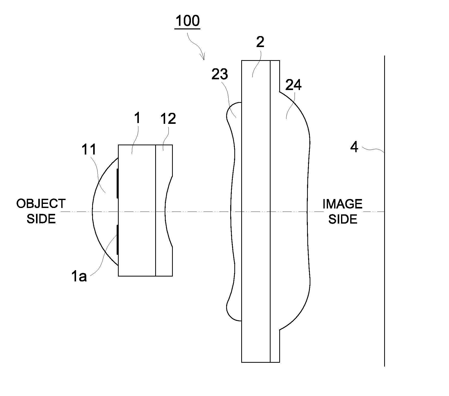
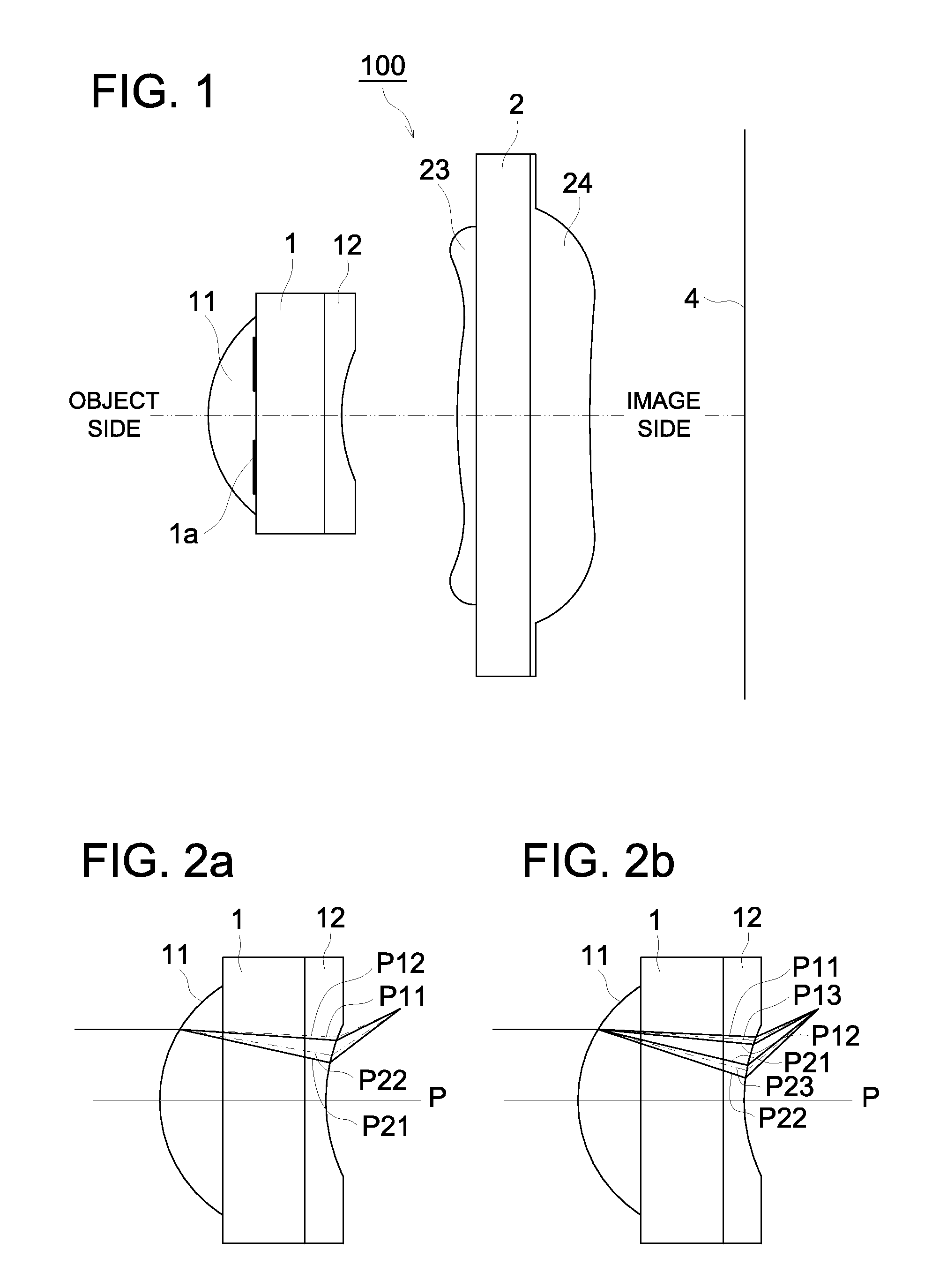
[0134]FIG. 1 is a diagram showing an image pickup lens relating to Embodiment 1.

[0135]Image pickup lens 100 is arranged in an image pickup apparatus. In the image pickup apparatus, there is arranged an image sensor of a CCD type or of a CMOS type. An image of an object image is formed on image sensor 4 by the image pickup lens 100. The image pickup apparatus is arranged in a mobile terminal such as a cell-phone and a PDA.

[0136]In the image pickup lens 100 relating to the present embodiment, first lens substrate 1 is arranged on the side of an object representing a photographic subject, and second lens substrate 2 is arranged on the image side that is behind the first lens substrate 1. The first lens substrate 1 and the second lens substrate 2 are arranged with the predetermined distance between them. The first lens substrate 1 and the second lens substrate 2 are formed into parallel flat plates. On the image side of the second lens substrate 2, there is arranged image sensor 4 of a ...

embodiment 2

[0176]FIG. 16 is a diagram showing an image pickup lens relating to Embodiment 2.

[0177]In image pickup lens 100 relating to Embodiment 2, there are arranged an aperture stop 1a on the object side, first lens substrate 1 on the image side and the rear of the aperture stop, and optical member 7 in a form of a parallel flat plate on the image side and the rear of the first lens substrate. On the first lens substrate 1, first lens 11 and second lens 12 which are the same as those in Embodiment 1 are formed. In image pickup lens 100 of such the structure, optical member 7 arranged at the closest position to the image side causes negative distortion to reduce positive distortion caused by the negative power of the second lens 12. Further, when curvature of field is caused, it keeps a sagittal image plane and a meridional image plane in a balanced manner. The wording saying that “when curvature of field is caused” in this case means a situation wherein both of the sagittal image plane and ...

example

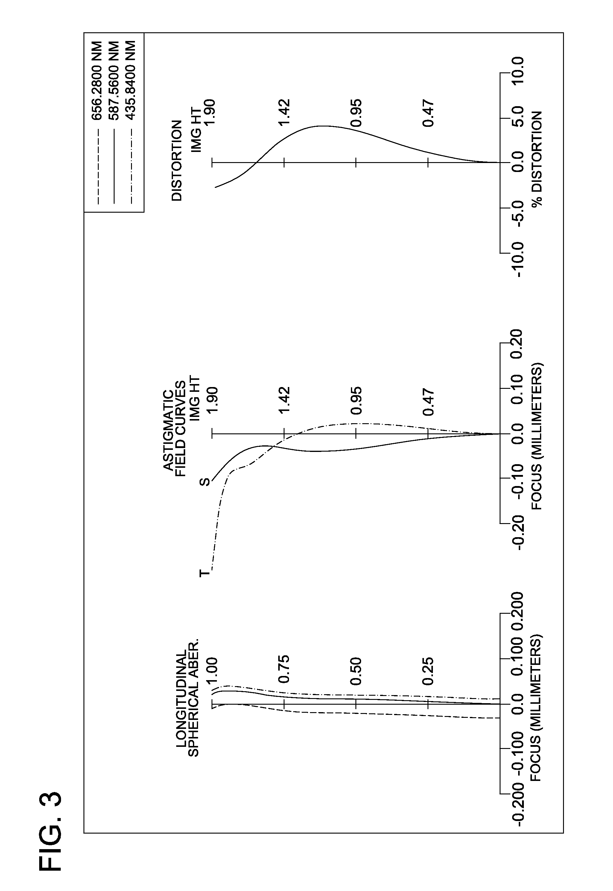
[0188]Data and measurement results of aberrations of respective examples and variation examples of image pickup lens 100 relating to Embodiment 1 and Embodiment 2 will be shown below. The examples use the following signs.

[0189]R: Curvature radius of lens (mm)

[0190]D: Axial distance of lens surfaces (mm)

[0191]Nd: Refractive index of lens

[0192]ν: Abbe number of lens

[0193]In each example, a form of an aspheric surface is represented by the following expression (14) which is an expression of a displacement amount X of the aspheric surface, where a tip of the surface is the origin, the X axis extends in a direction of the optical axis, and h is a height along a perpendicular direction to the optical axis.

[Math.28]X=h2 / R1+1-(1+K)h2 / R2+∑Aihi(14)

[0194]In the aforesaid expression, Ai represents an aspheric surface coefficient of ith order (where i=4, 6, 8 . . . ), and K represents a conic constant.

[0195]Aberrations were measured and the difference dν between Abbe number ν1 of the first lens ...


PUM

PropertyMeasurementUnit
Timeaaaaaaaaaa
Sizeaaaaaaaaaa
Lengthaaaaaaaaaa

Abstract

Provided is an imaging lens using a wafer scale lens which can easily be produced in a mass production. The entire optical length can be reduced without increasing a lens substrate or a lens formed on the substrate or without using a diffracting plane. The aberration can be preferably corrected. The imaging lens forms a first lens having a positive refractive power and Abbe number v1 on the object side and a second lens having a negative refractive power and Abbe number v2 on the image side of the first lens substrate. The difference between the Abbe number v1 and the Abbe number (v1−v2) is set to be a value greater than 10.

Description

TECHNICAL FIELD[0001]The present invention relates to an image pickup lens for an image pickup apparatus that employs a solid-state imaging device such as an image sensor of a CCD type and an image sensor of a CMOS type and that is capable of being mounted on a mobile terminal.BACKGROUND ART[0002]A small-sized and thin-type image pickup apparatus has been mounted on a mobile terminal representing a small-sized and thin-type electronic instrument such as a cell-phone and a PDA (Personal Digital Assistant), which has made it possible to transmit not only voice information but also image information to the remote place one another.[0003]As image sensors used for these image pickup apparatuses, there are used solid-state imaging devices including an image sensor of a CCD (Charge Coupled Device) type and an image sensor of a CMOS (Complementary Metal-Oxide Semiconductor) type. As a lens for forming a subject image on the image sensor, lenses which are made of resins on a mass production ...

Claims


Application Information

Patent Timeline
IPC IPC(8): G02B9/04
CPCB82Y20/00G02B7/028G02B13/0025G02B13/003Y10T29/49826G02B13/006G02B13/0085Y10T156/1052G02B13/0035G03B30/00G02B13/0045G02B9/12
Inventor HIRAO, YUSUKEMATSUSAKA, KEIJI
Owner KONICA MINOLTA OPTO
Why Eureka
Try Eureka